Method 202 -
Determination of Condensable Particulate Emissions from Stationary Sources
1.
APPLICABILITY AND PRINCIPLE
5.2.1 Post-test N2
Purge for Sources Emitting SO2.
5.2.2.1 Container Nos.
1, 2, and 3.
5.2.2.2 Container No. 4
(Impinger Contents).
5.2.2.3 Container No. 5
(MeCl2 Rinse).
5.2.2.4 Container No. 6
(Water Blank).
5.2.2.5 Container No. 7
(MeCl2 Blank).
5.3.1 Container Nos. 1,
2, and 3.
5.3.2.2 Organic
Fraction Weight Determination (Organic Phase from Container Nos. 4 and 5).
5.3.2.3 Inorganic
Fraction Weight Determination.
5.3.2.4 Analysis of
Sulfate by IC to Determine Ammonium Ion (NH4 +) Retained in the
Sample.
5.3.3 Analysis of Water
and MeCl2 Blanks (Container Nos. 6 and 7).
5.3.4 Analysis of
Acetone Blank (Container No. 8).
7.2 Correction for NH4
+ and H2O.
8.1 Determination of
NH4+ Retained in Sample by
Titration.
8.2 Analysis of
Chlorides by IC.
8.3 Air Purge to Remove
SO 2 from Impinger Contents.
8.4 Chloroform-ether
Extraction.
8.5 Improving
Collection Efficiency.
1. APPLICABILITY AND PRINCIPLE
1.1 Applicability.
1.1.1 This method applies to the determination of
condensable particulate matter (CPM) emissions from stationary sources. It is
intended to represent condensable matter as material that condenses after
passing through a filter and as measured by this method (Note: The filter catch can be analyzed according to the
appropriate method).
1.1.2 This method may be used in conjunction with Method
201 or 201A if the probes are glass-lined. Using Method 202 in conjunction with
Method 201 or 201A, only the impinger train configuration and analysis is
addressed by this method. The sample train operation and front-end recovery and
analysis shall be conducted according to Method 201 or 201A.
1.1.3 This method may also be modified to measure material
that condenses at other temperatures by specifying the filter and probe
temperature. A heated Method 5 out-of-stack filter may be used instead of the
in-stack filter to determine condensable emissions at wet sources.
1.2 Principle.
1.2.1 The CPM is collected in the impinger portion of a
Method 17 (Appendix A, 40 CFR Part 60) type sampling train. The impinger
contents are immediately purged after the run with nitrogen (N2) to remove dissolved sulfur dioxide (SO2) gases from
the impinger contents. The impinger solution is then extracted with methylene
chloride (MeCl2). The organic and aqueous fractions are then taken
to dryness and the residues weighed. The total of both fractions represents the
CPM.
1.2.2 The potential for low collection efficiency exist at
oil-fired boilers. To improve the collection efficiency at these type of
sources, an additional filter placed between the second and third impinger is
recommended.
2. PRECISION AND INTERFERENCE
2.1 Precision.
The precision based on
method development tests at an oil-fired boiler and a catalytic cracker were
11.7 and 4.8 percent, respectively.
2.2 Interference.
Ammonia. In sources that
use ammonia injection as a control technique for hydrogen chloride (HCl), the
ammonia interferes by reacting with HCl in the gas stream to form ammonium
chloride (NH4Cl) which would be measured as CPM. The sample may be
analyzed for chloride and the equivalent amount of NH4Cl can be subtracted from the CPM weight. However, if NH4Cl is to be counted as CPM, the inorganic fraction should be taken to
near dryness (less than 1 ml liquid) in the oven and then allowed to air dry at
ambient temperature to prevent any NH4Cl from vaporizing.
3. APPARATUS
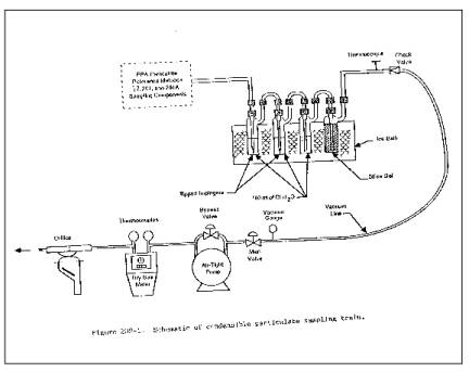
3.1 Sampling Train.
Same as in Method 17,
Section 2.1, with the following exceptions noted below (see Figure 202-1). Note:
Mention of trade names or specific
products does not constitute endorsement by EPA.
3.1.1 The probe extension shall be glass-lined or Teflon.
3.1.2 Both the first and second impingers shall be of the
Greenburg-Smith design with the standard tip.
Figure 202-1. Schematic of Condensable Particulate
Sampling Train
3.1.3 All sampling train glassware shall be cleaned prior
to the test with soap and tap water, water, and rinsed using tap water, water,
acetone, and finally, MeCl2. It is important to completely remove all silicone
grease from areas that will be exposed to the MeCl2 during sample recovery.
3.2 Sample Recovery.
Same as in Method 17,
Section 2.2, with the following additions:
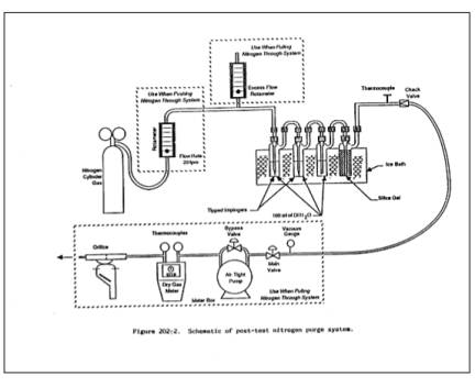
3.2.1 N2 Purge Line.
Inert tubing and fittings
capable of delivering 0 to 28 liters/min of N2 gas to the
impinger train from a standard gas cylinder (see Figure 202-2). Standard 0.95
cm (3/8-inch) plastic tubing and compression fittings in conjunction with an
adjustable pressure regulator and needle valve may be used.
3.2.2 Rotameter.
Capable of measuring gas
flow at 20 liters/min.
Figure 202-2. Schematic of Post-Test Nitrogen Purge
System
3.3 Analysis.
The following equipment is
necessary in addition to that listed in Method 17, Section 2.3:
3.3.1 Separatory
Funnel. Glass, 1-liter.
3.3.2 Weighing Tins. 350-ml.
3.3.3 Drying Equipment.
Hot plate and oven with temperature
control.
3.3.4 Pipets. 5-ml.
3.3.5 Ion
Chromatograph. Same as in Method 5F,
Section 2.1.6.
4. REAGENTS
Unless otherwise
indicated, all reagents must conform to the specifications established by the
Committee on Analytical Reagents of the American Chemical Society. Where such
specifications are not available, use the best available grade.
4.1 Sampling.
Same as in Method 17,
Section 3.1, with the addition of deionized distilled water to conform to the
American Society for Testing and Materials Specification D 1193-74, Type II and
the omittance of Section 3.1.4.
4.2 Sample Recovery.
Same as in Method 17,
Section 3.2, with the following additions:
4.2.1 N2 Gas.
Zero grade N2 gas at delivery pressures high enough to provide a
flow of 20 liters/min for 1 hour through the sampling train.
4.2.2 Methylene
Chloride, ACS grade. Blanks shall be
run prior to use and only methylene chloride with low blank values (0.001
percent) shall be used.
4.2.3 Water. Same as in Section 4.1.
4.3 Analysis. Same as in Method 17, Section 3.3, with the
following additions:
4.3.1 Methylene
Chloride. Same as Section 4.2.2.
4.3.2 Ammonium
Hydroxide. Concentrated (14.8 M) NH4OH.
4.3.3 Water. Same as in Section 4.1.
4.3.4 Phenolphthalein. The pH indicator solution, 0.05 percent in 50 percent
alcohol.
5. PROCEDURE
5.1 Sampling.
Same as in Method 17,
Section 4.1, with the following exceptions:
5.1.1 Place 100 ml of water in the first three impingers.
5.1.2 The use of silicone grease in train assembly is not
recommended because it is very soluble in MeCl2 which may
result in sample contamination. Teflon tape or similar means may be used to
provide leak-free connections between glassware.
5.2 Sample Recovery.
Same as in Method 17,
Section 4.2 with the addition of a post-test N2 purge and
specific changes in handling of individual samples as described below.
5.2.1 Post-test N2 Purge for Sources Emitting SO2.
(Note: This step is recommended, but is optional. When
little or no SO2 is present in the gas stream, i.e., the pH of the
impinger solution is greater than 4.5, purging has been found to be
unnecessary.) As soon as possible after the post-test leak check, detach the
probe and filter from the impinger train. Leave the ice in the impinger box to
prevent removal of moisture during the purge. If necessary, add more ice during
the purge to maintain the gas temperature below 20˚C. With no flow of gas
through the clean purge line and fittings, attach it to the input of the
impinger train (see Figure 202-2). To avoid over- or under-pressurizing the
impinger array, slowly commence the N2 gas flow through
the line while simultaneously opening the meter box pump valve(s). Adjust the
pump bypass and N2 delivery rates to obtain the following conditions:
(1) 20 liters/min or •H
@ and (2) an overflow rate through the
rotameter of less than 2 liters/min. Condition (2) guarantees that the N2 delivery system is operating at greater than ambient pressure and
prevents that possibility of passing ambient air (rather than N2) through the impingers. Continue the purge under these conditions for 1
hour, checking the rotameter and •H value(s) periodically. After 1 hour,
simultaneously turn off the delivery and pumping systems.
5.2.2 Sample Handling.
5.2.2.1 Container Nos. 1, 2, and 3.
If filter catch is to be
determined, as detailed in Method 17, Section 4.2.
5.2.2.2 Container No. 4 (Impinger Contents).
Measure the liquid in the
first three impingers to within 1 ml using a clean graduated cylinder or by
weighing it to within 0.5 g using a balance. Record the volume or weight of
liquid present to be used to calculate the moisture content of the effluent
gas. Quantitatively transfer this liquid into a clean sample bottle (glass or
plastic); rinse each impinger and the connecting glassware, including probe
extension, twice with water, recover the rinse water, and add it to the same
sample bottle. Mark the liquid level on the bottle.
5.2.2.3 Container No. 5 (MeCl2 Rinse).
Follow the water rinses of
each impinger and the connecting glassware, including the probe extension with
two rinses of MeCl2; save the rinse products in a clean, glass sample
jar. Mark the liquid level on the jar.
5.2.2.4 Container No. 6 (Water Blank).
Once during each field
test, place 500 ml of water in a separate sample container.
5.2.2.5 Container No. 7 (MeCl2 Blank).
Once during each field
test, place in a separate glass sample jar a volume of MeCl2 approximately equivalent to the volume used to conduct the MeCl2 rinse of the impingers.
5.3 Analysis.
Record the data required
on a sheet such as the one shown in Figure 202-3. Handle each sample container
as follows:
5.3.1 Container Nos. 1, 2, and 3.
If filter catch is
analyzed, as detailed in Method 17, Section 4.3.
5.3.2 Container Nos. 4 and 5.
Note the level of liquid
in the containers and confirm on the analytical data sheet whether leakage
occurred during transport. If a noticeable amount of leakage has occurred,
either void the sample or use methods, subject to the approval of the
Administrator, to correct the final results. Measure the liquid in Container
No. 4 either volumetrically to +1 ml or gravimetrically to +0.5
g. Remove a 5-ml aliquot and set aside for later ion chromatographic (IC)
analysis of sulfates. (Note: Do
not use this aliquot to determine chlorides since the HCl will be evaporated
during the first drying step; Section 8.2 details a procedure for this
analysis.)
5.3.2.1 Extraction.
Separate the organic
fraction of the sample by adding the contents of Container No. 5 (MeCl2) to the contents of Container No. 4 in a 1000-ml separatory funnel.
After mixing, allow the aqueous and organic phases to fully separate, and drain
off most of the organic/MeCl2 phase. Then add 75 ml of MeCl2 to the funnel, mix well, and drain off the lower organic phase. Repeat
with another 75 ml of MeCl2. This extraction should yield about 250 ml of
organic extract. Each time, leave a small amount of the organic/MeCl2 phase in the separatory funnel ensuring that no water is collected in
the organic phase. Place the organic extract in a tared 350-ml weighing tin.
5.3.2.2 Organic Fraction Weight Determination (Organic Phase from Container Nos. 4 and 5).
Evaporate the organic
extract at room temperature and pressure in a laboratory hood. Following
evaporation, desiccate the organic fraction for 24 hours in a desiccator
containing anhydrous calcium sulfate. Weigh to a constant weight and report the
results to the nearest 0.1 mg.
5.3.2.3 Inorganic Fraction Weight Determination.
[Note: If NH4Cl is to be counted
as CPM, the inorganic fraction should be taken to near dryness (less than 1 ml
liquid) in the oven and then allow to air dry at ambient temperature. If
multiple acid emissions are suspected, the ammonia titration procedure in
Section 8.1 may be preferred.] Using a hot plate, or equivalent, evaporate the
aqueous phase to approximately 50 ml; then, evaporate to dryness in a 105˚C
oven. Redissolve the residue in 100 ml of water. Add five drops of
phenolphthalein to this solution; then, add concentrated (14.8 M) NH4OH until the sample turns pink. Any excess NH40H will be evaporated during the drying step. Evaporate the sample to
dryness in a 105˚C oven, desiccate the sample for 24 hours, weigh to a constant
weight, and record the results to the nearest 0.1 mg. (Note: The addition of NH4OH is
recommended, but is optional when little or no SO2 is present in
the gas stream, i.e., when the pH of the impinger solution is greater than 4.5,
the addition of NH4OH is not necessary.)
5.3.2.4 Analysis of Sulfate by IC to Determine Ammonium Ion (NH4 +) Retained in the Sample.
(Note: If NH4OH is not added,
omit this step.) Determine the amount of sulfate in the aliquot taken from
Container No. 4 earlier as described in Method 5F (Appendix A, 40 CFR Part 60).
Based on the IC SO4-2 analysis of the aliquot, calculate the correction
factor to subtract the NH4+ retained in the sample and to add the combined water
removed by the acid-base reaction (see Section 7.2).
5.3.3 Analysis of Water and MeCl2 Blanks (Container Nos. 6 and 7).
Analyze these sample
blanks as described above in Sections 5.3.2.3 and 5.3.2.2, respectively.
5.3.4 Analysis of Acetone Blank (Container No. 8).
Same as in Method 17,
Section 4.3.
6. CALIBRATION
Same as in Method 17,
Section 5, except for the following:
6.1 IC Calibration.
Same as Method 5F, Section
5.
6.2 Audit Procedure.
Concurrently, analyze the
audit sample and a set of compliance samples in the same manner to evaluate the
technique of the analyst and the standards preparation. The same analyst,
analytical reagents, and analytical system shall be used both for compliance
samples and the EPA audit sample. If this condition is met, auditing of
subsequent compliance analyses for the same enforcement agency within 30 days
is not required. An audit sample set may not be used to validate different sets
of compliance samples under the jurisdiction of different enforcement agencies,
unless prior arrangements are made with both enforcement agencies.
6.3 Audit Samples.
Audit Sample Availability.
Audit samples will be supplied only to enforcement agencies for compliance
tests. The availability of audit samples may be obtained by writing:
Source Test Audit
Coordinator (MD-77B)
Quality Assurance Division
Atmospheric Research and
Exposure Assessment Laboratory
U.S. Environmental
Protection Agency
Research Triangle Park, NC
27711
or by calling the Source
Test Audit Coordinator (STAC) at (919) 541-7834. The request for the audit
sample must be made at least 30 days prior to the scheduled compliance sample
analysis.
6.4 Audit Results.
Calculate the audit sample
concentration according to the calculation procedure described in the audit
instructions included with the audit sample. Fill in the audit sample
concentration and the analyst's name on the audit response form included with
the audit instructions. Send one copy to the EPA Regional Office or the
appropriate enforcement agency and a second copy to the STAC. The EPA Regional
Office or the appropriate enforcement agency will report the results of the
audit to the laboratory being audited. Include this response with the results
of the compliance samples in relevant reports to the EPA Regional Office or the
appropriate enforcement agency.
7. CALCULATIONS
Same as in Method 17,
Section 6, with the following additions:
7.1 Nomenclature.
Same as in Method 17,
Section 6.1 with the following additions.
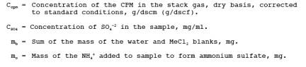
7.2 Correction for NH4 + and H2O.
Calculate the correction
factor to subtract the NH4+
retained in the sample based on the IC
SO4 -2 and if desired, add the combined water removed by
the acid-base reaction.
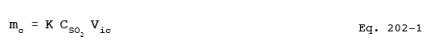
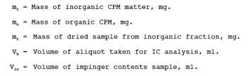
7.3 Mass of Inorganic CPM.
![]()
7.4 Concentration of CPM.
8. ALTERNATIVE PROCEDURES
8.1 Determination of NH4+ Retained in Sample by Titration.
8.1.1 An alternative procedure to determine the amount of
NH4+ added to the inorganic fraction by titration may be
used. After dissolving the inorganic residue in 100 ml of water, titrate the
solution with 0.1 N NH4OH to a pH of 7.0, as indicated by a pH meter. The
0.1 N NH4OH is made as follows: Add 7 ml of concentrated (14.8
M) NH4OH to l liter of water. Standardize against
standardized 0.1 N H2 SO4 and calculate the exact
normality using a procedure parallel to that described in Section 5.5 of Method
6 (Appendix A, 40 CFR Part 60). Alternatively, purchase 0.1 N NH4OH that has been standardized against a National Institute of Standards
and Technology reference material.
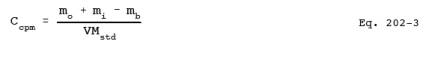
8.1.2 Calculate the concentration of SO4-2 in the
sample using the following equation.
8.1.3 Calculate the CPM as described in Section 7.
8.2 Analysis of Chlorides by IC.
At the conclusion of the
final weighing as described in Section 5.3.2.3, redissolve the inorganic
fraction in 100 ml of water. Analyze an aliquot of the redissolved sample for
chlorides by IC using techniques similar to those described in Method 5F for
sulfates. Previous drying of the sample should have removed all HCl. Therefore,
the remaining chlorides measured by IC can be assumed to be NH4Cl, and this weight can be subtracted from the weight determined for
CPM.
8.3 Air Purge to Remove SO 2 from Impinger Contents.
As an alternative to the
post-test N2 purge described in Section 5.2.1, the tester may opt
to conduct the post-test purge with air at 20 liter/min. Note: The use of an air purge is not as effective as a N2 purge.
8.4 Chloroform-ether Extraction.
As an alternative to the
methylene chloride extraction described in Section 5.3.2.1, the tester may opt
to conduct a chloroform-ether extraction.
Note: The chloroform-ether was not as effective as the MeCl2 in removing the organics, but it was found to be an acceptable organic
extractant. Chloroform and diethlyether of ACS grade, with low blank values
(0.001 percent), shall be used. Analysis of the chloroform and diethlyether
blanks shall be conducted according to Section 5.3.3 for MeCl2.
8.4.1 Add the contents of Container No. 4 to a 1000-ml
separatory funnel. Then add 75 ml of chloroform to the funnel, mix well, and
drain off the lower organic phase. Repeat two more times with 75 ml of
chloroform. Then perform three extractions with 75 ml of diethylether. This
extraction should yield approximately 450 ml of organic extraction. Each time,
leave a small amount of the organic/MeCl2 phase in the
separatory funnel ensuring that no water is collected in the organic phase.
8.4.2 Add the contents of Container No. 5 to the organic
extraction. Place approximately 300 ml of the organic extract in a tared 350-ml
weighing tin while storing the remaining organic extract in a sample container.
As the organic extract evaporates, add the remaining extract to the weighing
tin.
8.4.3 Determine the weight of the organic phase as described
in Section 5.3.2.2.
8.5 Improving Collection Efficiency.
If low impinger collection
efficiency is suspected, the following procedure may be used.
8.5.1 Place an out-of-stack filter as described in Method 8
between the second and third impingers.
8.5.2 Recover and anaylze the filter according to Method
17, Section 4.2. Include the filter holder as part of the connecting glassware
and handle as described in Sections 5.2.2.2 and 5.2.2.3.
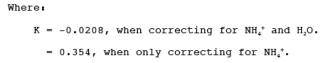
8.5.3 Calculate the Concentration of CPM as follows:
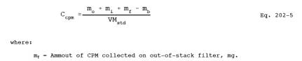
8.6 Wet Source Testing.
When testing at a wet
source, use a heated outof-stack filter as described in Method 5.
9. BIBLIOGRAPHY
1. DeWees, W.D., S.C.
Steinsberger, G.M. Plummer, L.T. Lay, G.D. McAlister, and R.T. Shigehara.
"Laboratory and Field Evaluation of the EPA Method 5 Impinger Catch for
Measuring Condensable Matter from Stationary Sources." Paper presented at
the 1989 EPA/AWMA International Symposium on Measurement of Toxic and Related
Air Pollutants. Raleigh, North Carolina. May 1-5, 1989.
2. DeWees, W.D. and K.C. Steinsberger. "Method
Development and Evaluation of Draft Protocol for Measurement of Condensable
Particulate Emissions." Draft Report. November 17, 1989.
3. Texas Air Control Board, Laboratory Division.
"Determination of Particulate in Stack Gases Containing Sulfuric Acid
and/or Sulfur Dioxide." Laboratory Methods for Determination of Air
Pollutants. Modified December 3, 1976.
4. Nothstein, Greg. Masters Thesis. University of
Washington. Department of Environmental Health. Seattle, Washington.
5. "Particulate Source Test Procedures Adopted by
Puget Sound Air Pollution Control Agency Board of Directors." Puget Sound
Air Pollution Control Agency, Engineering Division. Seattle, Washington. August
11, 1983.
6. Commonwealth of Pennsylvania, Department of
Environmental Resources. Chapter 139, Sampling and Testing (Title 25, Rules and
Regulations, Part I, Department of Environmental Resources, Subpart C,
Protection of Natural Resources, Article III, Air Resources). January 8, 1960.
7. Wisconsin Department of Natural Resources. Air
Management Operations Handbook, Revision 3. January 11, 1988.
Figure 202-3.
Analytical data sheet
Moisture Determination
Volume or weight of liquid
in impingers_______________ ml or g
Weight of moisture in
silica gel_______________________ g
Sample Preparation
(Container No. 4)
Amount of liquid lost
during transport________________ ml
Final volume
_________________________________________ ml
pH of sample prior to
analysis________________________
Addition of NH4OH required? __________________________
Sample extracted 2X with
75 ml MeCl2 ? ________________
For Titration of
Sulfate
Normality of NH4OH ___________________________________ N
Volume of sample titrated
____________________________ ml
Volume of titrant ____________________________________
ml
Sample Analysis
______________________________________________________
Weight of Condensable
Particulate, mg
Container
__________________________________________
number Final Weight Tare
Weight Weight Gain
_______________________________________________________
4 (Inorganic)
4 & 5 (Organic)
_______________________________________________________
Total _____________
Less Blank _____________
Weight of Condensable
Particulate _____________
_______________________