METHOD
17 - DETERMINATION OF PARTICULATE MATTER EMISSIONS FROM STATIONARY SOURCES
NOTE: This method does not include all of the
specifications (e.g.,
equipment and supplies) and procedures (e.g., sampling and analytical) essential to its
performance. Some material is incorporated by reference from other methods in
this part. Therefore, to obtain reliable results, persons using this method
should have a thorough knowledge of at least the following additional test
methods: Method 1, Method 2,
Method 3, Method 5.
8.0 Sample Collection,
Preservation, Storage, and Transport.
8.1.2 Preliminary
Determinations.
8.1.3 Preparation of
Sampling Train.
8.1.5 Sampling Train
Operation.
8.1.6 Calculation of Percent
Isokinetic.
9.0 Quality Control.
[Reserved]
10.0 Calibration and
Standardization.
12.0 Data Analysis and
Calculations.
13.0 Method
Performance. [Reserved]
14.0 Pollution
Prevention. [Reserved]
15.0 Waste Management.
[Reserved]
18.0 Tables, Diagrams,
Flowcharts, and Validation Data.
1.0 Scope and Application.
1.1 Analyte.
Particulate matter
(PM). No CAS number assigned.
NOTE: Particulate matter is not an absolute quantity.
It is a function of temperature and pressure. Therefore, to prevent variability
in PM emission regulations and/or associated test methods, the temperature and
pressure at which PM is to be measured must be carefully defined. Of the two
variables (i.e., temperature
and pressure), temperature has the greater effect upon the amount of PM in an
effluent gas stream; in most stationary source categories, the effect of
pressure appears to be negligible. In Method 5, 120 °C (248 °F) is established
as a nominal reference temperature. Thus, where Method 5 is specified in an
applicable subpart of the standard, PM is defined with respect to temperature.
In order to maintain a collection temperature of 120 °C (248 °F), Method 5
employs a heated glass sample probe and a heated filter holder. This equipment
is somewhat cumbersome and requires care in its operation. Therefore, where PM
concentrations (over the normal range of temperature associated with a
specified source category) are known to be independent of temperature, it is
desirable to eliminate the glass probe and the heating systems, and to sample
at stack temperature.
1.2 Applicability.
This method is
applicable for the determination of PM emissions, where PM concentrations are
known to be independent of temperature over the normal range of temperatures
characteristic of emissions from a specified source category. It is intended to
be used only when specified by an applicable subpart of the standards, and only
within the applicable temperature limits (if specified), or when otherwise
approved by the Administrator. This method is not applicable to stacks that
contain liquid droplets or are saturated with water vapor. In addition, this
method shall not be used as written if the projected cross-sectional area of
the probe extension-filter holder assembly covers more than 5 percent of the
stack cross-sectional area (see Section 8.1.2).
1.3 Data Quality Objectives.
Adherence to the
requirements of this method will enhance the quality of the data obtained from
air pollutant sampling methods.
2.0 Summary of Method.
2.1
Particulate matter is withdrawn isokinetically from the source and collected on
a glass fiber filter maintained at stack temperature. The PM mass is determined
gravimetrically after the removal of uncombined water.
3.0 Definitions.
Same as Method 5, Section 3.0.
4.0 Interferences. [Reserved]
5.0 Safety.
5.1 Disclaimer. This method
may involve hazardous materials, operations, and equipment. This test method
may not address all of the safety problems associated with its use. It is the
responsibility of the user of this test method to establish appropriate safety
and health practices and determine the applicability of regulatory limitations
prior to performing this test method.
6.0 Equipment and Supplies.
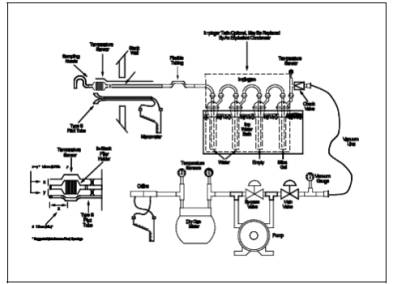
6.1 Sampling Train.
A schematic of the
sampling train used in this method is shown in Figure 17-1.
The sampling train components and operation and maintenance are very similar to
Method 5, which should be consulted for details.
6.1.1 Probe Nozzle,
Differential Pressure Gauge, Metering System, Barometer, Gas Density
Determination Equipment. Same as in Method 5,
Sections 6.1.1, 6.1.4, 6.1.8, 6.1.9, and
6.1.10, respectively.
6.1.2 Filter Holder.
The in-stack filter holder shall be constructed of borosilicate or quartz glass,
or stainless steel. If a gasket is used, it shall be made of silicone rubber,
Teflon, or stainless steel. Other holder and gasket materials may be used,
subject to the approval of the Administrator. The filter holder shall be
designed to provide a positive seal against leakage from the outside or around
the filter.
6.1.3 Probe
Extension. Any suitable rigid probe extension may be used after the filter
holder.
6.1.4 Pitot Tube.
Same as in Method 5, Section 6.1.3.
6.1.4.1 It is
recommended (1) that the pitot tube have a known baseline coefficient,
determined as outlined in Section 10 of Method 2;
and (2) that this known coefficient be preserved by placing the pitot tube in
an interference-free arrangement with respect to the sampling nozzle, filter
holder, and temperature sensor (see Figure 17-1). Note that the 1.9 cm
(3/4-in.) free-space between the nozzle and pitot tube shown in Figure 17-1, is
based on a 1.3 cm (1/2-in.) ID nozzle.
If the sampling train is designed for sampling at higher flow rates than
that described in APTD- 0581, thus necessitating the use of larger sized
nozzles, the free-space shall be 1.9 cm (3/4-in.) with the largest sized nozzle
in place.
6.1.4.2
Source-sampling assemblies that do not meet the minimum spacing requirements of
Figure 17-1 (or the equivalent of these requirements, e.g., Figure 2-4 of
Method 2) may be used; however, the pitot tube coefficients of such
assemblies shall be determined by calibration, using methods subject to the
approval of the Administrator.
6.1.5 Condenser. It
is recommended that the impinger system or alternatives described in Method 5
be used to determine the moisture content of the stack gas. Flexible tubing may
be used between the probe extension and condenser. Long tubing lengths may
affect the moisture determination.
6.2 Sample Recovery.
Probe-liner and
probe-nozzle brushes, wash bottles, glass sample storage containers, petri
dishes, graduated cylinder and/or balance, plastic storage containers, funnel
and rubber policeman, funnel. Same as in Method
5, Sections 6.2.1 through 6.2.8, respectively.
6.3 Sample Analysis.
Glass weighing
dishes, desiccator, analytical balance, balance, beakers, hygrometer,
temperature sensor. Same as in Method 5, Sections
6.3.1 through 6.3.7, respectively.
7.0 Reagents and Standards.
7.1 Sampling.
Filters, silica gel,
water, crushed ice, stopcock grease. Same as in Method
5, Sections 7.1.1, 7.1.2, 7.1.3, 7.1.4, and 7.1.5, respectively. Thimble
glass fiber filters may also be used.
7.2 Sample Recovery.
Acetone (reagent
grade). Same as in Method 5, Section 7.2.
7.3 Sample Analysis.
Acetone and
Desiccant. Same as in Method 5, Sections 7.3.1
and 7.3.2, respectively.
8.0 Sample Collection, Preservation, Storage, and Transport.
8.1 Sampling.
8.1.1 Pretest Preparation.
Same as in Method 5, Section 8.1.1.
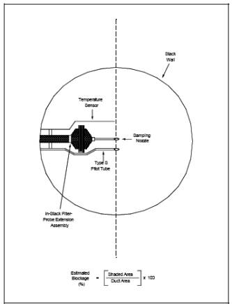
8.1.2 Preliminary Determinations.
Same as in Method 5,
Section 8.1.2, except as follows: Make a projected-area model of the probe
extension-filter holder assembly, with the pitot tube face openings positioned
along the centerline of the stack, as shown in Figure 17-2.
Calculate the estimated cross-section blockage, as shown in Figure 17-2. If the
blockage exceeds 5 percent of the duct cross sectional area, the tester has the
following options exist: (1) a suitable out-of-stack filtration method may be
used instead of in-stack filtration; or (2) a special in-stack rrangement, in
which the sampling and velocity measurement sites are separate, may be used;
for details concerning this approach, consult with the Administrator (see also Reference 1 in Section 17.0). Select a probe extension
length such that all traverse points can be sampled. For large stacks, consider
sampling from opposite sides of the stack to reduce the length of probes.
8.1.3 Preparation of Sampling Train.
Same as in Method 5,
Section 8.1.3, except the following: Using a tweezer or clean disposable
surgical gloves, place a labeled (identified) and weighed filter in the filter
holder. Be sure that the filter is properly centered and the gasket properly
placed so as not to allow the sample gas stream to circumvent the filter. Check
filter for tears after assembly is completed. Mark the probe extension with
heat resistant tape or by some other method to denote the proper distance into
the stack or duct for each sampling point. Assemble the train as in Figure
17-1, using a very light coat of silicone grease on all ground glass joints and
greasing only the outer portion (see APTD-0576) to avoid possibility of
contamination by the silicone grease. Place crushed ice around the impingers.
8.1.4 Leak-Check Procedures.
Same as in Method 5,
Section 8.1.4, except that the filter holder is inserted into the stack during
the sampling train leak-check. To do this, plug the inlet to the probe nozzle
with a material that will be able to withstand the stack temperature. Insert
the filter holder into the stack and wait approximately 5 minutes (or longer,
if necessary) to allow the system to come to equilibrium with the temperature
of the stack gas stream.
8.1.5 Sampling Train Operation.
The operation is the
same as in Method 5. Use a data sheet such as the one shown in Figure 5-3 of Method 5, except that the filter
holder temperature is not recorded.
8.1.6 Calculation of Percent Isokinetic.
Same as in Method 5, Section 12.11.
8.2 Sample Recovery.
8.2.1 Proper cleanup
procedure begins as soon as the probe extension assembly is removed from the
stack at the end of the sampling period. Allow the assembly to cool.
8.2.2 When the
assembly can be safely handled, wipe off all external particulate matter near
the tip of the probe nozzle and place a cap over it to prevent losing or
gaining particulate matter. Do not cap off the probe tip tightly while the
sampling train is cooling down as this would create a vacuum in the filter
holder, forcing condenser water backward.
8.2.3 Before moving
the sample train to the cleanup site, disconnect the filter holder-probe nozzle
assembly from the probe extension; cap the open inlet of the probe extension.
Be careful not to lose any condensate, if present. Remove the umbilical cord
from the condenser outlet and cap the outlet. If a flexible line is used
between the first impinger (or condenser) and the probe extension, disconnect
the line at the probe extension and let any condensed water or liquid drain
into the impingers or condenser. Disconnect the probe extension from the
condenser; cap the probe extension outlet. After wiping off the silicone
grease, cap off the condenser inlet. Ground glass stoppers, plastic caps, or
serum caps (whichever are appropriate) may be used to close these openings.
8.2.4 Transfer both
the filter holder-probe nozzle assembly and the condenser to the cleanup area.
This area should be clean and protected from the wind so that the chances of
contaminating or losing the sample will be minimized.
8.2.5 Save a portion
of the acetone used for cleanup as a blank. Take 200 ml of this acetone from
the wash bottle being used and place it in a glass sample container labeled
"acetone blank." Inspect the train prior to and during disassembly
and not any abnormal conditions. Treat the sample as discussed in Method 5,
Section 8.2.
9.0 Quality Control. [Reserved]
10.0 Calibration and Standardization.
The calibrations of
the probe nozzle, pitot tube, metering system, temperature sensors, and
barometer are the same as in Method 5, Sections
10.1 through 10.3, 10.5, and 10.6, respectively.
11.0 Analytical Procedure.
Same as in Method 5, Section 11.0. Analytical data should be
recorded on a form similar to that shown in Figure
5-6 of Method 5.
12.0 Data Analysis and Calculations.
Same as in Method 5, Section 12.0.
13.0 Method Performance. [Reserved]
14.0 Pollution Prevention. [Reserved]
15.0 Waste Management. [Reserved]
16.0 Alternative Procedures.
Same as in Method 5, Section 16.0.
17.0 References.
Same as in Method 5, Section 17.0, with the addition of the
following:
1.
Vollaro, R.F. Recommended Procedure for Sample Traverses in Ducts Smaller than
12 Inches in Diameter. U.S. Environmental Protection Agency, Emission
Measurement
Branch. Research
Triangle Park, NC. November 1976.
18.0 Tables, Diagrams, Flowcharts, and Validation Data.
Figure
17-1. Particulate Matter Sampling Train with In-Stack Filter.
Figure
17-2. Projected-Area Model of Cross-Section Blockage (approximate average for a
sample traverse) Caused by an In-Stack Filter Holder-Probe Extension Assembly.