METHOD
8 - DETERMINATION OF SULFURIC ACID AND SULFUR
DIOXIDE
EMISSIONS FROM STATIONARY SOURCES
NOTE: This method does not include all of the
specifications (e.g.,
equipment and supplies) and procedures (e.g., sampling and analytical) essential to its performance.
Some material is incorporated by reference from other methods in this part.
Therefore, to obtain reliable results, persons using this method should have a
thorough knowledge of at least the following additional test methods: Method 1, Method 2, Method 3, Method 5, and Method 6.
8.0 Sample Collection,
Preservation, Storage, and Transport.
8.2 Preliminary
Determinations.
8.3 Preparation of
Sampling Train.
8.4 Metering System
Leak-Check Procedure.
8.5 Pretest Leak-Check
Procedure.
8.7 Calculation of
Percent Isokinetic.
9.1 Miscellaneous
Quality Control Measures.
9.2 Volume Metering
System Checks.
10.0 Calibration and
Standardization.
12.0 Data Analysis and
Calculations.
12.2 Average Dry Gas
Meter Temperature and Average Orifice Pressure Drop.
12.4 Volume of Water
Vapor Condensed and Moisture Content.
12.5 Sulfuric Acid Mist
(Including SO3) Concentration.
12.6 Sulfur Dioxide
Concentration.
12.8 Stack Gas Velocity
and Volumetric Flow Rate.
12.9 Relative Error
(RE) for QA Audit Samples.
14.0 Pollution
Prevention. [Reserved]
15.0 Waste Management.
[Reserved]
17.0 Tables, Diagrams,
Flowcharts, and Validation Data.
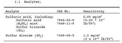
1.0 Scope and Application.
1.1 Analytes.
1.2 Applicability.
This method is
applicable for the determination of H2SO4 (including H2SO4 mist and SO3)
and gaseous SO2 emissions from stationary sources.
NOTE: Filterable particulate matter may be
determined along with H2SO4 and
SO2 (subject to the approval of the
Administrator) by inserting a heated glass fiber filter between the probe and
isopropanol impinger (see Section 6.1.1 of
Method 6). If this option is chosen, particulate analysis is gravimetric only;
sulfuric acid is not determined separately.
1.3 Data Quality Objectives.
Adherence to the
requirements of this method will enhance the quality of the data obtained from
air pollutant sampling methods.
2.0 Summary of Method.
A gas sample is
extracted isokinetically from the stack. The H2SO4 and the SO2 are
separated, and both fractions are measured separately by the barium-thorin
titration method.
3.0 Definitions. [Reserved]
4.0 Interferences.
4.1 Possible
interfering agents of this method are fluorides, free ammonia, and dimethyl
aniline. If any of these interfering agents is present (this can be determined
by knowledge of the process), alternative methods, subject to the approval of
the Administrator, are required.
5.0 Safety.
5.1 Disclaimer.
This method may
involve hazardous materials, operations, and equipment. This test method may
not address all of the safety problems associated with its use. It is the
responsibility of the user of this test method to establish appropriate safety
and health practices and determine the applicability of regulatory limitations
prior to performing this test method.
5.2 Corrosive reagents.
Same as Method 6, Section 5.2.
6.0 Equipment and Supplies.
6.1 Sample Collection.
Same as Method 5, Section 6.1, with the following
additions and exceptions:
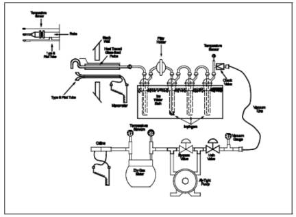
6.1.1 Sampling
Train. A schematic of the sampling train used in this method is shown in Figure
8-1; it is similar to the Method 5 sampling train, except that the filter
position is different, and the filter holder does not have to be heated. See
Method 5, Section 6.1.1, for details and guidelines on operation and
maintenance.
6.1.1.1 Probe
Liner. Borosilicate or quartz glass, with a heating system to prevent visible
condensation during sampling. Do not use metal probe liners.
6.1.1.2 Filter
Holder. Borosilicate glass, with a glass frit filter support and a silicone
rubber gasket. Other gasket materials (e.g., Teflon or Viton) may be used, subject to
the approval of the Administrator. The holder design shall provide a positive
seal against leakage from the outside or around the filter. The filter holder
shall be placed between the first and second impingers. Do not heat the filter
holder.
6.1.1.3 Impingers.
Four, of the Greenburg-Smith design, as shown in Figure
8-1. The first and third impingers must have standard tips. The second and
fourth impingers must be modified by replacing the insert with an approximately
13-mm (1/2-in.) ID glass tube, having an unconstricted tip located 13 mm (1/2
in.) from the bottom of the impinger. Similar collection systems, subject to
the approval of the Administrator, may be used.
6.1.1.4
Temperature Sensor. Thermometer, or equivalent, to measure the temperature of
the gas leaving the impinger train to within 1 °C (2 °F).
6.2 Sample Recovery.
The following
items are required for sample recovery:
6.2.1 Wash
Bottles. Two polyethylene or glass bottles, 500-ml.
6.2.2 Graduated
Cylinders. Two graduated cylinders (volumetric flasks may be used), 250-ml,
1-liter.
6.2.3 Storage
Bottles. Leak-free polyethylene bottles, 1-liter size (two for each sampling
run).
6.2.4 Trip
Balance. 500-g capacity, to measure to ± 0.5 g (necessary only if a moisture
content analysis is to be done).
6.3 Analysis.
The following
items are required for sample analysis:
6.3.1 Pipettes.
Volumetric 10-ml, 100-ml.
6.3.2 Burette.
50-ml.
6.3.3 Erlenmeyer
Flask. 250-ml (one for each sample, blank, and standard).
6.3.4 Graduated
Cylinder. 100-ml.
6.3.5 Dropping
Bottle. To add indicator solution, 125-ml size.
7.0 Reagents and Standards.
NOTE: Unless otherwise indicated, all reagents are
to conform to the specifications established by the Committee on Analytical
Reagents of the American Chemical Society, where such specifications are
available. Otherwise, use the best available grade.
7.1 Sample Collection.
The following
reagents are required for sample collection:
7.1.1 Filters and
Silica Gel. Same as in Method 5, Sections 7.1.1
and 7.1.2, respectively.
7.1.2 Water. Same
as in Method 6, Section 7.1.1.
7.1.3 Isopropanol,
80 Percent by Volume. Mix 800 ml of isopropanol with 200 ml of water.
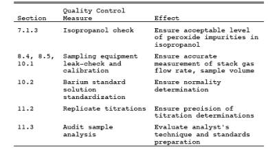
NOTE: Check for peroxide impurities using the procedure
outlined in Method 6, Section 7.1.2.1.
7.1.4 Hydrogen
Peroxide (H2O2), 3
Percent by Volume. Dilute 100 ml of 30 percent H2O2 to 1 liter with water. Prepare fresh daily.
7.1.5 Crushed Ice.
7.2 Sample Recovery.
The reagents and
standards required for sample recovery are:
7.2.1 Water. Same
as in Section 7.1.2.
7.2.2 Isopropanol,
80 Percent. Same as in Section 7.1.3.
7.3 Sample Analysis.
Same as Method 6, Section 7.3.
7.3.1 Quality
Assurance Audit Samples. When making compliance determinations, and upon
availability, audit samples may be obtained from the appropriate EPA Regional
Office or from the responsible enforcement authority.
NOTE: The responsible enforcement authority should
be notified at least 30 days prior to the test date to allow sufficient time
for sample delivery.
8.0 Sample Collection, Preservation, Storage, and Transport.
8.1 Pretest Preparation.
Same as Method 5, Section 8.1, except that filters
should be inspected but need not be desiccated, weighed, or identified. If the
effluent gas can be considered dry (i.e., moisture-free), the silica gel need not be weighed.
8.2 Preliminary Determinations.
Same as Method 5, Section 8.2.
8.3 Preparation of Sampling Train.
Same as Method 5, Section 8.3, with the following
exceptions:
8.3.1 Use Figure 8-1 instead of Figure 5-1.
8.3.2 Replace the
second sentence of Method 5, Section 8.3.1 with: Place 100 ml of 80 percent
isopropanol in the first impinger, 100 ml of 3 percent H2O2 in
both the second and third impingers; retain a portion of each reagent for use
as a blank solution. Place about 200 g of silica gel in the fourth impinger.
8.3.3 Ignore any
other statements in Section 8.3 of Method 5 that are obviously not applicable
to the performance of Method 8.
NOTE: If moisture content is to be determined by
impinger analysis, weigh each of the first three impingers (plus absorbing
solution) to the nearest 0.5 g, and record these weights. Weigh also the silica
gel (or silica gel plus container) to the nearest 0.5 g, and record.)
8.4 Metering System Leak-Check Procedure.
Same as Method 5, Section 8.4.1.
8.5 Pretest Leak-Check Procedure.
Follow the basic
procedure in Method 5, Section 8.4.2, noting that the probe heater shall be
adjusted to the minimum temperature required to prevent condensation, and also
that verbiage such as "...plugging the inlet to the filter holder..."
found in Section 8.4.2.2 of Method 5 shall be replaced by "...plugging the
inlet to the first impinger...". The pretest leak-check is recommended,
but is not required.
8.6 Sampling Train Operation.
Follow the basic
procedures in Method 5, Section 8.5, in
conjunction with the following special instructions:
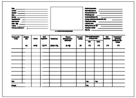
8.6.1 Record the
data on a sheet similar to that shown in Figure 8-2
(alternatively, Figure 5-2 in Method 5 may be
used). The sampling rate shall not exceed 0.030 m3/min
(1.0 cfm) during the run. Periodically during the test, observe the connecting
line between the probe and first impinger for signs of condensation. If
condensation does occur, adjust the probe heater setting upward to the minimum
temperature required to prevent condensation. If component changes become
necessary during a run, a leak-check shall be performed immediately before each
change, according to the procedure outlined in Section
8.4.3 of Method 5 (with appropriate modifications, as mentioned in Section
8.5 of this method); record all leak rates. If the leakage rate(s) exceeds the
specified rate, the tester shall either void the run or plan to correct the
sample volume as outlined in Section 12.3 of
Method 5. Leak-checks immediately after component changes are recommended,
but not required. If these leak-checks are performed, the procedure in Section
8.4.2 of Method 5 (with appropriate modifications) shall be used.
8.6.2 After
turning off the pump and recording the final readings at the conclusion of each
run, remove the probe from the stack. Conduct a post-test (mandatory)
leak-check as outlined in Section 8.4.4 of Method 5 (with appropriate
modifications), and record the leak rate. If the post-test leakage rate exceeds
the specified acceptable rate,
either correct the sample volume, as outlined in Section 12.3 of Method
5, or void the run.
8.6.3 Drain the
ice bath and, with the probe disconnected, purge the remaining part of the
train by drawing clean ambient air through the system for 15 minutes at the
average flow rate used for sampling.
NOTE: Clean ambient air can be provided by passing
air through a charcoal filter. Alternatively, ambient air (without cleaning)
may be used.
8.7 Calculation of Percent Isokinetic.
Same as Method 5, Section 8.6.
8.8 Sample Recovery.
Proper cleanup
procedure begins as soon as the probe is removed from the stack at the end of
the sampling period. Allow the probe to cool. Treat the samples as follows:
8.8.1 Container
No. 1.
8.8.1.1 If a
moisture content analysis is to be performed, clean and weigh the first
impinger (plus contents) to the nearest
0.5 g, and record this weight.
8.8.1.2 Transfer
the contents of the first impinger to a 250-ml graduated cylinder. Rinse the probe, first impinger,
all connecting glassware before the filter, and the front half of the filter
holder with 80 percent isopropanol. Add the isopropanol rinse solution to the
cylinder. Dilute the contents of the cylinder to 225 ml with 80 percent
isopropanol, and transfer the cylinder contents to the storage container. Rinse the cylinder with 25 ml of 80
percent isopropanol, and transfer the rinse to the storage container. Add the filter to the solution in the
storage container and mix. Seal the container to protect the solution against
evaporation. Mark the level of liquid on the container, and identify the sample
container.
8.8.2 Container
No. 2.
8.8.2.1 If a
moisture content analysis is to be performed, clean and weigh the second and
third impingers (plus contents) to the nearest 0.5 g, and record the weights. Also, weigh the spent silica
gel (or silica gel plus impinger) to the nearest 0.5 g, and record the weight.
8.8.2.2 Transfer
the solutions from the second and third impingers to a 1-liter graduated
cylinder. Rinse all connecting glassware (including back half of filter holder)
between the filter and silica gel impinger with water, and add this rinse water
to the cylinder. Dilute the contents of the cylinder to 950 ml with water.
Transfer the solution to a storage container. Rinse the cylinder with 50 ml of
water, and transfer the rinse to the storage container. Mark the level of liquid on the
container. Seal and identify the sample container.
9.0 Quality Control.
9.1 Miscellaneous Quality Control Measures.
9.2 Volume Metering System Checks.
Same as Method 5, Section 9.2.
10.0 Calibration and Standardization.
10.1 Sampling
Equipment. Same as Method 5, Section 10.0.
10.2 Barium Standard
Solution. Same as Method 6, Section 10.5.
11.0 Analytical Procedure.
11.1. Sample Loss.
Same as Method 6, Section 11.1.
11.2. Sample Analysis.
11.2.1 Container
No. 1. Shake the container holding the isopropanol solution and the filter. If
the filter breaks up, allow the fragments to settle for a few minutes before
removing a sample aliquot. Pipette a 100-ml aliquot of this solution into a
250-ml Erlenmeyer flask, add 2 to 4 drops of thorin indicator, and titrate to a
pink endpoint using 0.0100 N barium standard solution. Repeat the titration
with a second aliquot of sample, and average the titration values. Replicate
titrations must agree within 1 percent or 0.2 ml, whichever is greater.
11.2.2 Container
No. 2. Thoroughly mix the solution in the container holding the contents of the
second and third impingers. Pipette a 10-ml aliquot of sample into a 250-ml Erlenmeyer
flask. Add 40 ml of isopropanol, 2 to 4 drops of thorin indicator, and titrate
to a pink endpoint using 0.0100 N barium standard solution. Repeat the
titration with a second aliquot of sample, and average the titration values.
Replicate titrations must agree within 1 percent or 0.2 ml, whichever is
greater.
11.2.3 Blanks.
Prepare blanks by adding 2 to 4 drops of thorin indicator to 100 ml of 80
percent isopropanol. Titrate the blanks in the same manner as the samples.
11.3 Audit Sample Analysis.
11.3.1 When the
method is used to analyze samples to demonstrate compliance with a source
emission regulation, EPA audit samples must be analyzed, subject to
availability.
11.3.2
Concurrently analyze audit samples and the compliance samples in the same
manner to evaluate the technique of the analyst and the standards preparation.
NOTE: It is recommended that known quality control
samples be analyzed prior to the compliance and audit sample analyses to
optimize the system accuracy and precision. These quality control samples may be obtained by contacting
the appropriate EPA regional Office or the responsible enforcement authority.
11.3.3 The same
analyst, analytical reagents, and analytical system shall be used for the
compliance samples and the EPA audit samples. If this condition is met,
duplicate auditing of subsequent compliance analyses for the same enforcement
agency within a 30-day period is waived.
Audit samples may not be used to validate different compliance samples
under the jurisdiction of separate enforcement agencies, unless prior
arrangements have been made with both enforcement agencies.
11.4 Audit Sample Results.
11.4.1 Calculate
the audit sample concentrations in mg/dscm and submit results using the
instructions provided with the audit samples.
11.4.2 Report the
results of the audit samples and the compliance determination samples along
with their identification numbers, and the analyst's name to the responsible
enforcement authority. Include this information with reports of any subsequent
compliance analyses for the same enforcement authority during the 30-day
period.
11.4.3 The
concentrations of the audit samples obtained by the analyst shall agree within
5 percent of the actual concentrations. If the 5 percent specification is not
met, reanalyze the compliance and audit samples, and include initial and
reanalysis values in the test report.
11.4.4 Failure to
meet the 5 percent specification may require retests until the audit problems
are resolved. However, if the
audit results do not affect the compliance or noncompliance status of the
affected facility, the Administrator may waive the reanalysis requirement,
further audits, or retests and accept the results of the compliance test. While
steps are being taken to resolve audit analysis problems, the Administrator may
also choose to use the data to determine the compliance or noncompliance status
of the affected facility.
12.0 Data Analysis and Calculations.
Carry out
calculations retaining at least one extra significant figure beyond that of the
acquired data. Round off figures after final calculation.
12.1 Nomenclature.
Same as Method 5, Section 12.1, with the following
additions and exceptions:
Ca = Actual concentration of SO2 in audit sample, mg/dscm.
Cd = Determined concentration of SO2 in audit sample, mg/dscm.
CH2SO4 = Sulfuric acid (including SO3) concentration, g/dscm (lb/dscf).
CSO2 = Sulfur dioxide concentration, g/dscm
(lb/dscf).
N = Normality of
barium perchlorate titrant, meq/ml.
RE = Relative
error of QA audit sample analysis, percent
Va = Volume of sample aliquot titrated, 100 ml
for H2SO4 and
10 ml for SO2.
Vsoln = Total volume of solution in which the
sample is contained, 250 ml for the SO2 sample
and 1000 ml for the H2SO4 sample.
Vt = Volume of barium standard solution titrant
used for the sample, ml.
Vtb = Volume of barium standard solution titrant
used for the blank, ml.
12.2 Average Dry Gas Meter Temperature and Average Orifice Pressure Drop.
See data sheet (Figure 8-2).
12.3 Dry Gas Volume.
Same as Method 5,
Section 12.3.
12.4 Volume of Water Vapor Condensed and Moisture Content.
Calculate the
volume of water vapor using Equation 5-2 of Method
5; the weight of water collected in the impingers and silica gel can be
converted directly to milliliters (the specific gravity of water is 1 g/ml).
Calculate the moisture content of the stack gas (Bws) using Equation 5-3 of Method 5. The NOTE
in Section 12.5 of Method 5 also applies to this
method. Note that if the effluent gas stream can be considered dry, the volume
of water vapor and moisture content need not be calculated.
12.5 Sulfuric Acid Mist (Including SO3)
Concentration.
![]()
where:
K3 = 0.04904 g/meq for metric units,
= 1.081 x 10⁻⁴ lb/meq for English units.
12.6 Sulfur Dioxide Concentration.
![]()
where:
K4 = 0.03203 g/meq for metric units,
= 7.061 x 10⁻⁵ lb/meq for English units.
12.7 Isokinetic Variation.
Same as Method 5, Section 12.11.
12.8 Stack Gas Velocity and Volumetric Flow Rate.
Calculate the average
stack gas velocity and volumetric flow rate, if needed, using data obtained in
this method and the equations in Sections 12.6
and 12.7 of Method 2.
12.9 Relative Error (RE) for QA Audit Samples.
Same as Method 6, Section 12.4.
13.0 Method Performance.
13.1 Analytical Range.
Collaborative
tests have shown that the minimum detectable limits of the method are 0.06 mg/m3 (4 x 10⁻⁹ lb/ft3) for H2SO4 and 1.2 mg/m3 (74
x 10-9 lb/ft3)
for SO2. No upper limits have been established.
Based on theoretical calculations for 200 ml of 3 percent H2O2 solution,
the upper concentration limit for SO2 in
a 1.0 m3 (35.3 ft3)
gas sample is about 12,000 mg/m3 (7.7 x 10⁻⁴ lb/ft3). The
upper limit can be extended by increasing the quantity of peroxide solution in
the impingers.
14.0 Pollution Prevention. [Reserved]
15.0 Waste Management. [Reserved]
16.0 References.
Same as Section 17.0 of Methods 5 and 6.
17.0 Tables, Diagrams, Flowcharts, and Validation Data.
Figure
8-1. Sulfuric Acid Sampling Train.