METHOD 16B -
DETERMINATION OF TOTAL REDUCED SULFUR
EMISSIONS FROM
STATIONARY SOURCES
NOTE: This method does not include all of the
specifications (e.g.,
equipment and supplies) and procedures (e.g., sampling and analytical) essential to its
performance. Some material is incorporated by reference from other methods in
this part. Therefore, to obtain
reliable results, persons using this method should have a knowledge of at least
the following additional test methods: Method 6C, Method 16, and Method 16A.
8.0 Sample Collection,
Preservation, Storage, and Transport.
12.0 Data Analysis and
Calculations.
14.0 Pollution
Prevention. [Reserved]
15.0 Waste Management.
[Reserved]
17.0 Tables, Diagrams,
Flowcharts, and Validation Data.
1.0 Scope and Application.
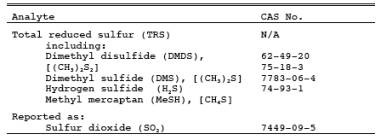
1.1 Analytes.
1.2 Applicability.
This method is
applicable for determining TRS emissions from recovery furnaces (boilers), lime
kilns, and smelt dissolving tanks at Kraft pulp mills, and from other sources
when specified in an applicable subpart of the regulations. The flue gas must
contain at least 1 percent oxygen for complete oxidation of all TRS to SO2.
1.3 Data Quality Objectives.
Adherence to the
requirements of this method will enhance the quality of the data obtained from
air pollutant sampling methods.
2.0 Summary of Method.
2.1 An integrated gas
sample is extracted from the stack. The SO2 is
removed selectively from the sample using a citrate buffer solution. The TRS
compounds are then thermally oxidized to SO2 and
analyzed as SO2 by gas chromatography (GC) using flame
photometric detection (FPD).
3.0 Definitions. [Reserved]
4.0 Interferences.
4.1 Reduced sulfur
compounds other than those regulated by the emission standards, if present, may
be measured by this method. Therefore, carbonyl sulfide, which is partially
oxidized to SO2 and may be present in a limekiln exit stack,
would be a positive interferant.
4.2 Particulate
matter from the limekiln stack gas (primarily calcium carbonate) can cause a
negative bias if it is allowed to enter the citrate scrubber; the particulate
matter will cause the pH to rise and H2S to be
absorbed before oxidation. Proper use of the particulate filter, described in Section 6.1.3 of Method 16A, will eliminate
this interference.
4.3 Carbon monoxide
(CO) and carbon dioxide (CO2) have substantial
desensitizing effects on the FPD even after dilution. Acceptable systems must
demonstrate that they have eliminated this interference by some procedure such
as eluting these compounds before the SO2.
Compliance with this requirement can be demonstrated by submitting
chromatograms of calibration gases with and without CO2 in diluent gas. The CO2 level
should be approximately 10 percent for the case with CO2 present. The two chromatograms should show agreement within the
precision limits of Section 13.0.
5.0 Safety.
5.1 Disclaimer. This
method may involve hazardous materials, operations, and equipment. This test
method may not address all of the safety problems associated with its use. It
is the responsibility of the user of this test method to establish appropriate
safety and health practices and determine the applicability of regulatory
limitations prior to performing this test method.
5.2 Hydrogen Sulfide
(H2S). A flammable, poisonous gas with the odor of
rotten eggs. H2S is extremely hazardous and can cause collapse,
coma, and death within a few seconds of one or two inhalations at sufficient
concentrations. Low concentrations irritate the mucous membranes and may cause
nausea, dizziness, and headache after exposure.
6.0 Equipment and Supplies.
6.1 Sample Collection.
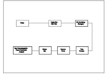
The sampling train is
shown in Figure 16B-1. Modifications to the apparatus
are accepted provided the system performance check in Section
8.4.1 is met.
6.1.1 Probe, Probe
Brush, Particulate Filter, SO2 Scrubber, Combustion
Tube, and Furnace. Same as in Method 16A,
Sections 6.1.1 to 6.1.6.
6.1.2 Sampling Pump. Leakless
Teflon-coated diaphragm type or equivalent.
6.2 Analysis.
6.2.1 Dilution System
(optional), Gas Chromatograph, Oven, Temperature Gauges, Flow System, Flame
Photometric Detector, Electrometer, Power Supply, Recorder, Calibration System,
Tube Chamber, Flow System, and Constant Temperature Bath. Same as in Method 16, Sections 6.2.1, 6.2.2, and 6.3.
6.2.2 Gas
Chromatograph Columns. Same as in Method 16, Section 6.2.3. Other columns with
demonstrated ability to resolve SO2 and be
free from known interferences are acceptable alternatives. Single column
systems such as a 7-ft Carbsorb B HT 100 column have been found satisfactory in
resolving SO2 from CO2.
7.0 Reagents and Standards.
Same as in Method 16, Section 7.0, except for the following:
7.1 Calibration Gas.
SO2 permeation tube gravimetrically calibrated and certified at some
convenient operating temperature. These tubes consist of hermetically sealed
FEP Teflon tubing in which a liquefied gaseous substance is enclosed. The
enclosed gas permeates through the tubing wall at a constant rate. When the
temperature is constant, calibration gases covering a wide range of known
concentrations can be generated by varying and accurately measuring the flow
rate of diluent gas passing over the tubes. In place of SO2 permeation tubes, cylinder gases containing SO2 in nitrogen may be used for calibration. The cylinder gas
concentration must be verified according to Section 8.2.1 of Method 6C. The
calibration gas is used to calibrate the GC/FPD system and the dilution system.
7.2 Recovery Check Gas.
7.2.1 Hydrogen
sulfide [100 parts per million by volume (ppmv) or less] in nitrogen, stored in
aluminum cylinders. Verify the concentration by Method
11, the procedure discussed in Section 16.0
of Method 16A, or gas chromatography where the instrument is calibrated
with an H2S permeation tube as described below. For the
wet chemical methods, the standard deviation should not exceed 5 percent on at
least three 20-minute runs.
7.2.2 Hydrogen
sulfide recovery gas generated from a permeation device gravimetrically
calibrated and certified at some convenient operation temperature may be used.
The permeation rate of the device must be such that at a dilution gas flow rate
of 3 liters/min (64 ft3/hr), an H2S
concentration in the range of the stack gas or within 20 percent of the
emission standard can be generated.
7.3 Combustion Gas.
Gas containing less
than 50 ppbv reduced sulfur compounds and less than 10 ppmv total hydrocarbons.
The gas may be generated from a clean-air system that purifies ambient air and
consists of the following components: diaphragm pump, silica gel drying tube,
activated charcoal tube, and flow rate measuring device. Gas from a compressed
air cylinder is also acceptable.
8.0 Sample Collection, Preservation, Storage, and Transport.
8.1 Pretest Procedures.
Same as in Method 15, Section 8.1.
8.2 Sample Collection.
Before any source
sampling is performed, conduct a system performance check as detailed in
Section 8.4.1 to validate the sampling train components and procedures.
Although this test is optional, it would significantly reduce the possibility
of rejecting tests as a result of failing the post-test performance check. At
the completion of the pretest system performance check, insert the sampling
probe into the test port making certain that no dilution air enters the stack
though the port. Condition the entire system with sample for a minimum of 15
minutes before beginning analysis. If the sample is diluted, determine the
dilution factor as in Section 10.4 of Method 15.
8.3 Analysis.
Inject aliquots of
the sample into the GC/FPD analyzer for analysis. Determine the concentration
of SO2 directly from the calibration curves or from the
equation for the least-squares line.
8.4. Post-Test Procedures
8.4.1
System Performance Check. Same as in Method
16A, Section 8.5. A sufficient number of sample injections should be made
so that the precision requirements of Section 13.2 are satisfied.
8.4.2 Determination of
Calibration Drift. Same as in Method 15,
Section 8.3.2.
9.0 Quality Control.
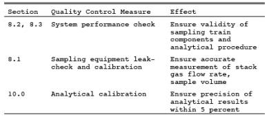
10.0 Calibration.
Same as in Method 16, Section 10, except SO2 is used instead of H2S.
11.0 Analytical Procedure.
11.1 Sample
collection and analysis are concurrent for this method (see section 8.3).
12.0 Data Analysis and Calculations.
12.1 Nomenclature.
CSO2 = Sulfur dioxide concentration, ppmv.
CTRS = Total reduced sulfur concentration as
determined by Equation 16B-1, ppmv.
d = Dilution factor,
dimensionless.
N = Number of
samples.
12.2 SO2 Concentration. Determine the concentration of SO2, CSO2, directly from the calibration curves. Alternatively, the concentration may be
calculated using the equation for the least-squares line.
12.3 TRS
Concentration.
![]()
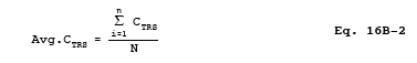
12.4 Average TRS
Concentration
13.0 Method Performance.
13.1 Range and
Sensitivity. Coupled with a GC using a 1-ml sample size, the maximum limit of
the FPD for SO2 is approximately 10 ppmv. This limit is extended
by diluting the sample gas before analysis or by reducing the sample aliquot
size. For sources with emission levels between 10 and 100 ppm, the measuring
range can be best extended by reducing the sample size.
13.2 GC/FPD
Calibration and Precision. A series of three consecutive injections of the
sample calibration gas, at any dilution, must produce results which do not vary
by more than 5 percent from the mean of the three injections.
13.3 Calibration
Drift. The calibration drift determined from the mean of the three injections
made at the beginning and end of any run or series of runs within a 24- hour
period must not exceed 5 percent.
13.4 System
Calibration Accuracy. Losses through the sample transport system must be
measured and a correction factor developed to adjust the calibration accuracy
to 100 percent.
13.5 Field tests
between this method and Method 16A showed an average difference of less than
4.0 percent. This difference was not determined to be significant.
14.0 Pollution Prevention. [Reserved]
15.0 Waste Management. [Reserved]
16.0 References.
1. Same as in Method 16, Section 16.0.
2. National Council
of the Paper Industry for Air and Stream Improvement, Inc, A Study of TRS
Measurement Methods. Technical Bulletin No. 434. New York, NY. May 1984. 12p.
3. Margeson, J.H.,
J.E. Knoll, and M.R. Midgett. A Manual Method for TRS Determination. Draft
available from the authors. Source Branch, Quality Assurance Division, U.S.
Environmental Protection Agency, Research Triangle Park, NC
17.0 Tables, Diagrams, Flowcharts, and Validation Data.
Figure
16B-1. Method 16B Sampling Train.