METHOD
16A - DETERMINATION OF TOTAL REDUCED SULFUR EMISSIONS FROM STATIONARY SOURCES
(IMPINGER TECHNIQUE)
NOTE: This method does not include all of the
specifications (e.g.,
equipment and supplies) and procedures (e.g., sampling and analytical) essential to its
performance. Some material is incorporated by reference from other methods in
this part. Therefore, to obtain reliable results, persons using this method
should have a thorough knowledge of at least the following additional test
methods: Method 1, Method 6,
and Method 16.
6.3 Sample Preparation
and Analysis.
7.1.3 Hydrogen
Peroxide, 3 percent.
7.2 Sample Recovery and
Analysis.
8.0 Sample Collection,
Preservation, Storage, and Transport.
8.1 Preparation of
Sampling Train.
8.2 Citrate Scrubber
Conditioning Procedure.
12.0 Data Analysis and
Calculations.
12.2 Dry Sample Gas
Volume, Corrected to Standard Conditions.
12.3 Concentration of
TRS as ppm SO2.
12.4 Concentration of
Recovery Gas Generated in the System Performance Check.
12.5 Recovery
Efficiency for the System Performance Check.
14.0 Pollution
Prevention. [Reserved]
15.0 Waste Management.
[Reserved]
16.11 Post-test Orifice
Calibration.
16.12 Calibrations and
Standardizations.
18.0 Tables, Diagrams,
Flowcharts, and Validation Data.
1.0 Scope and Application.
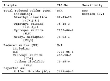
1.1 Analytes.
1.2 Applicability.
This method is
applicable for the determination of TRS emissions from recovery boilers, lime
kilns, and smelt dissolving tanks at kraft pulp mills, reduced sulfur compounds
(H2S, carbonyl sulfide, and carbon disulfide from
sulfur recovery units at onshore natural gas processing facilities, and from
other sources when specified in an applicable subpart of the regulations. The
flue gas must contain at least 1 percent oxygen for complete oxidation of all
TRS to SO2.
1.3 Data Quality Objectives.
Adherence to the
requirements of this method will enhance the quality of the data obtained from
air pollutant sampling methods.
2.0 Summary of Method.
2.1 An integrated gas
sample is extracted from the stack. SO2 is
removed selectively from the sample using a citrate buffer solution. TRS compounds
are then thermally oxidized to SO2,
collected in hydrogen peroxide as sulfate, and analyzed by the Method 6
barium-thorin titration procedure.
3.0 Definitions. [Reserved]
4.0 Interferences.
4.1 Reduced sulfur
compounds other than those regulated by the emission standards, if present, may
be measured by this method. Therefore, carbonyl sulfide, which is partially
oxidized to SO2 and may be present in a lime kiln exit stack,
would be a positive interferent.
4.2 Particulate
matter from the lime kiln stack gas (primarily calcium carbonate) can cause a
negative bias if it is allowed to enter the citrate scrubber; the particulate
matter will cause the pH to rise and H2S to be
absorbed prior to oxidation. Furthermore, if the calcium carbonate enters the
hydrogen peroxide impingers, the calcium will precipitate sulfate ion. Proper
use of the particulate filter described in Section 6.1.3 will eliminate this
interference.
5.0 Safety.
5.1 Disclaimer.
This method may
involve hazardous materials, operations, and equipment. This test method may
not address all of the safety problems associated with its use. It is the
responsibility of the user of this test method to establish appropriate safety
and health practices and determine the applicability of regulatory limitations
prior to performing this test method.
5.2 Corrosive reagents.
The following
reagents are hazardous. Personal protective equipment and safe procedures are
useful in preventing chemical splashes. If contact occurs, immediately flush
with copious amounts of water for at least 15 minutes. Remove clothing under
shower and decontaminate. Treat residual chemical burns as thermal burns.
5.2.1 Hydrogen
Peroxide (H2O2). Irritating to eyes,
skin, nose, and lungs.
5.2.2 Sodium
Hydroxide (NaOH). Causes severe damage to eyes and skin. Inhalation causes
irritation to nose, throat, and lungs. Reacts exothermically with limited
amounts of water.
5.2.3 Sulfuric Acid
(H2SO4). Rapidly
destructive to body tissue. Will cause third degree burns. Eye damage may
result in blindness. Inhalation may be fatal from spasm of the larynx, usually
within 30 minutes. May cause lung tissue damage with edema. 3 mg/m3 will cause lung damage in uninitiated. 1 mg/m3 for 8 hours will cause lung damage or, in higher concentrations,
death. Provide ventilation to limit inhalation. Reacts violently with metals
and organics.
5.3 Hydrogen Sulfide (H2S).
A flammable,
poisonous gas with the odor of rotten eggs. H2S is
extremely hazardous and can cause collapse, coma, and death within a few
seconds of one or two inhalations at sufficient concentrations. Low
concentrations irritate the mucous membranes and may cause nausea, dizziness,
and headache after exposure.
6.0 Equipment and Supplies.
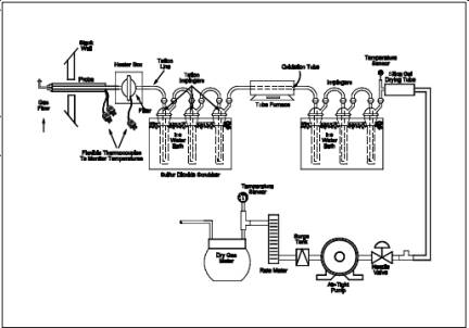
6.1 Sample Collection.
The sampling train is
shown in Figure 16A-1 and component parts are discussed
below. Modifications to this sampling train are acceptable provided the system
performance check is met (see Section 8.5).
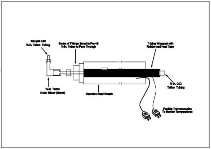
6.1.1 Probe.
Teflon tubing, 6.4-mm
(1/4-in.) diameter, sequentially wrapped with heat-resistant fiber strips, a
rubberized heat tape (plug at one end), and heat-resistant adhesive tape. A
flexible thermocouple or other suitable temperature-measuring device should be placed
between the Teflon tubing and the fiber strips so that the temperature can be
monitored to prevent softening of the probe. The probe should be sheathed in
stainless steel to provide in-stack rigidity. A series of bored-out stainless
steel fittings placed at the front of the sheath will prevent moisture and
particulate from entering between the probe and sheath. A 6.4-mm (1/4-in.)
Teflon elbow (bored out) should be attached to the inlet of the probe, and a
2.54 cm (1 in.) piece of Teflon tubing should be attached at the open end of
the elbow to permit the opening of the probe to be turned away from the
particulate stream; this will reduce the amount of particulate drawn into the
sampling train. The probe is depicted in Figure 16A-2.
6.1.2 Probe Brush.
Nylon bristle brush
with handle inserted into a 3.2-mm (c-in.) Teflon tubing. The Teflon tubing should be long enough to
pass the brush through the length of the probe.
6.1.3 Particulate Filter.
50-mm Teflon filter
holder and a 1- to 2-µm porosity, Teflon filter (available through Savillex
Corporation, 5325 Highway 101, Minnetonka, Minnesota 55343). The filter holder
must be maintained in a hot box at a temperature sufficient to prevent moisture
condensation. A temperature of 121 ˚C (250 ˚F) was found to be sufficient when
testing a lime kiln under sub-freezing ambient conditions.
6.1.4 SO2 Scrubber.
Three 300-ml Teflon
segmented impingers connected in series with flexible, thick-walled, Teflon
tubing. (Impinger parts and tubing available through Savillex.) The first two
impingers contain 100 ml of citrate buffer and the third impinger is initially
dry. The tip of the tube inserted into the solution should be constricted to
less than 3 mm (c in.) ID and should be immersed to a depth of at least 5 cm (2
in.).
6.1.5 Combustion Tube.
Quartz glass tubing
with an expanded combustion chamber 2.54 cm (1 in.) in diameter and at least
30.5 cm (12 in.) long. The tube ends should have an outside diameter of 0.6 cm
(1/4 in.) and be at least 15.3 cm (6 in.) long. This length is necessary to
maintain the quartz-glass connector near ambient temperature and thereby avoid
leaks. Alternatively, the outlet may be constructed with a 90-degree glass
elbow and socket that would fit directly onto the inlet of the first peroxide
impinger.
6.1.6 Furnace.
A furnace of
sufficient size to enclose the combustion chamber of the combustion tube with a
temperature regulator capable of maintaining the temperature
6.1.7 Peroxide Impingers, Stopcock Grease, Temperature Sensor, Drying Tube, Valve, Pump, and Barometer.
Same as Method 6, Sections 6.1.1.2, 6.1.1.4, 6.1.1.5,
6.1.1.6, 6.1.1.7, 6.1.1.8, and 6.1.2, respectively, except that the midget
bubbler of Method 6, Section 6.1.1.2 is not required.
6.1.8 Vacuum Gauge.
At least 760 mm Hg
(30 in. Hg) gauge.
6.1.9 Rate Meter.
Rotameter, or
equivalent, accurate to within 5 percent at the selected flow rate of
approximately 2 liters/min (4.2 ft3/hr).
6.1.10 Volume Meter.
Dry gas meter capable
of measuring the sample volume under the sampling conditions of 2 liters/min
(4.2 ft3/hr) with an accuracy of 2 percent.
6.2 Sample Recovery.
Polyethylene Bottles,
250-ml (one per sample).
6.3 Sample Preparation and Analysis.
Same as Method 6, Section 6.3, except a 10-ml buret
with 0.05-ml graduations is required, and the spectrophotometer is not needed.
7.0 Reagents and Standards.
NOTE: Unless otherwise indicated, all reagents must
conform to the specifications established by the Committee on Analytical
Reagents of the American Chemical Society. When such specifications are not
available, the best available grade must be used.
7.1 Sample Collection.
The following
reagents are required for sample analysis:
7.1.1 Water.
Same as in Method 6, Section 7.1.1.
7.1.2 Citrate Buffer.
Dissolve 300 g of
potassium citrate (or 284 g of sodium citrate) and 41 g of anhydrous citric
acid in 1 liter of water (200 ml is needed per test). Adjust the pH to between
5.4 and 5.6 with potassium citrate or citric acid, as required.
7.1.3 Hydrogen Peroxide, 3 percent.
Same as in Method 6,
Section 7.1.3 (40 ml is needed per sample).
7.1.4 Recovery Check Gas.
Hydrogen sulfide (100
ppmv or less) in nitrogen, stored in aluminum cylinders. Verify the
concentration by Method 11 or by gas chromatography
where the instrument is calibrated with an H2S
permeation tube as described below. For Method 11, the relative standard
deviation should not exceed 5 percent on at least three 20-minute runs.
NOTE: Alternatively, hydrogen sulfide recovery gas
generated from a permeation device gravimetrically calibrated and certified at
some convenient operating temperature may be used. The permeation rate of the
device must be such that at a dilution gas flow rate of 3 liters/min (6.4 ft3/hr), an H2S concentration in the range of the stack gas or
within 20 percent of the standard can be generated.
7.1.5 Combustion Gas.
Gas containing less
than 50 ppb reduced sulfur compounds and less than 10 ppmv total hydrocarbons.
The gas may be generated from a clean-air system that purifies ambient air and
consists of the following components: Diaphragm pump, silica gel drying tube,
activated charcoal tube, and flow rate measuring device. Flow from a compressed
air cylinder is also acceptable.
7.2 Sample Recovery and Analysis.
Same as Method 6, Sections 7.2.1 and 7.3, respectively.
8.0 Sample Collection, Preservation, Storage, and Transport.
8.1 Preparation of Sampling Train.
8.1.1 For the SO2 scrubber, measure 100 ml of citrate buffer into the first and
second impingers; leave the third impinger empty. Immerse the impingers in an
ice bath, and locate them as close as possible to the filter heat box. The
connecting tubing should be free of loops. Maintain the probe and filter
temperatures sufficiently high to prevent moisture condensation, and monitor
with a suitable temperature sensor.
8.1.2 For the Method
6 part of the train, measure 20 ml of 3 percent hydrogen peroxide into the
first and second midget impingers. Leave the third midget impinger empty, and
place silica gel in the fourth midget impinger. Alternatively, a silica gel
drying tube may be used in place of the fourth impinger. Maintain the oxidation
furnace at 800 ± 100 ˚C (1472 ± 180 ˚F). Place crushed ice and water around all
impingers.
8.2 Citrate Scrubber Conditioning Procedure.
Condition the citrate
buffer scrubbing solution by pulling stack gas through the Teflon impingers and
bypassing all other sampling train components. A purge rate of 2 liters/min for
10 minutes has been found to be sufficient to obtain equilibrium. After the
citrate scrubber has been conditioned, assemble the sampling train, and conduct
(optional) a leak-check as described in Method 6,
Section 8.2.
8.3 Sample Collection.
Same as in Method 6,
Section 8.3, except the sampling rate is 2 liters/min (± 10 percent) for 1 or 3
hours. After the sample is collected, remove the probe from the stack, and
conduct (mandatory) a post-test leak-check as described in Method 6, Section
8.2. The 15-minute purge of the train following collection should not be
performed. After each 3-hour test run (or after three 1-hour samples), conduct
one system performance check (see Section 8.5) to determine the reduced sulfur
recovery efficiency through the sampling train. After this system performance
check and before the next test run, rinse and brush the probe with water,
replace the filter, and change the citrate scrubber (optional but recommended).
NOTE: In Method 16, a test run is composed of 16
individual analyses (injects) performed over a period of not less than 3 hours
or more than 6 hours. For Method 16A to be consistent with Method 16, the
following may be used to obtain a test run: (1) collect three 60-minute samples
or (2) collect one 3-hour sample. (Three test runs constitute a test.)
8.4 Sample Recovery.
Disconnect the
impingers. Quantitatively transfer the contents of the midget impingers of the
Method 6 part of the train into a leak-free polyethylene bottle for shipment.
Rinse the three midget impingers and the connecting tubes with water and add
the washings to the same storage container. Mark the fluid level. Seal and
identify the sample container.
8.5 System Performance Check.
8.5.1 A system
performance check is done (1) to validate the sampling train components and
procedure (prior to testing; optional) and (2) to validate a test run (after a
run). Perform a check in the field prior to testing consisting of a least two
samples (optional), and perform an additional check after each 3 hour run or
after three 1-hour samples (mandatory).
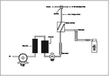
8.5.2 The checks
involve sampling a known concentration of H2S and
comparing the analyzed concentration with the known concentration. Mix the H2S recovery check gas (Section 7.1.4) and combustion gas in a
dilution system such as that shown in Figure 16A-3.
Adjust the flow rates to generate an H2S
concentration in the range of the stack gas or within 20 percent of the
applicable standard and an oxygen concentration greater than 1 percent at a
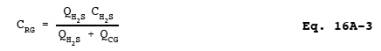
total flow rate of at least 2.5 liters/min (5.3 ft3/hr). Use Equation 16A-3 to calculate
the concentration of recovery gas generated. Calibrate the flow rate from both
sources with a soap bubble flow meter so that the diluted concentration of H2S can be accurately calculated.
8.5.3 Collect
30-minute samples, and analyze in the same manner as the emission samples.
Collect the sample through the probe of the sampling train using a manifold or
some other suitable device that will ensure extraction of a representative
sample.
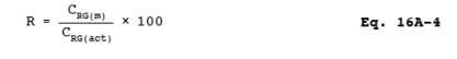
8.5.4 The recovery
check must be performed in the field prior to replacing the SO2 scrubber and particulate filter and before the probe is cleaned.
Use Equation 16A-4 (see Section 12.5) to calculate the recovery efficiency.
Report the recovery efficiency with the emission data; do not correct the
emission data for the recovery efficiency. A sample recovery of 100 ± 20
percent must be obtained for the emission data to be valid. However, if the
recovery efficiency is not in the 100 ± 20 percent range but the results do not
affect the compliance or noncompliance status of the affected facility, the
Administrator may decide to accept the results of the compliance test.
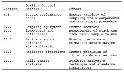
9.0 Quality Control.
10.0 Calibration.
Same as Method 6, Section 10.0.
11.0 Analytical Procedure.
11.1 Sample Loss
Check and Sample Analysis. Same as Method 6,
Sections 11.1 and 11.2, respectively, with the following exception: for
1-hour sampling, take a 40-ml aliquot, add 160 ml of 100 percent isopropanol
and four drops of thorin.
11.2 Audit Sample
Analysis. Same as Method 6, Section 11.3.
12.0 Data Analysis and Calculations.
In the calculations,
at least one extra decimal figure should be retained beyond that of the
acquired data. Figures should be rounded off after final calculations.
12.1 Nomenclature.
CTRS = Concentration of TRS as SO2, dry basis corrected to standard conditions, ppmv.
CRG(act) = Actual concentration of recovery check gas
(after dilution), ppm.
CRG(m) = Measured concentration of recovery check gas
generated, ppm.
CH2S = Verified
concentration of H2S recovery gas.
N = Normality of
barium perchlorate titrant, milliequivalents/ml.
Pbar = Barometric pressure at exit orifice of the dry
gas meter, mm Hg (in. Hg).
Pstd = Standard absolute pressure, 760 mm Hg (29.92
in. Hg).
QH2S = Calibrated flow
rate of H2S recovery gas, liters/min.
QCG = Calibrated flow rate of combustion gas,
liters/min.
R = Recovery
efficiency for the system performance check, percent.
Tm = Average dry gas meter absolute temperature, ˚K (˚R).
Tstd = Standard absolute temperature, 293 ˚K,
(528˚R).
Va = Volume of sample aliquot titrated, ml.
Vm = Dry gas volume as measured by the dry gas meter, liters (dcf).
Vm(std) = Dry gas volume measured by the dry gas meter,
corrected to standard conditions, liters (dscf).
Vsoln = Total volume of solution in which the sulfur
dioxide sample is contained, 100 ml.
Vt = Volume of barium perchlorate titrant used for the sample, ml
(average of replicate titrations).
Vtb = Volume of barium perchlorate titrant used for
the blank, ml.
Y = Dry gas meter
calibration factor.
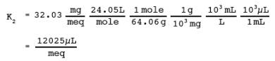
32.03 = Equivalent weight
of sulfur dioxide, mg/meq.
12.2 Dry Sample Gas Volume, Corrected to Standard Conditions.
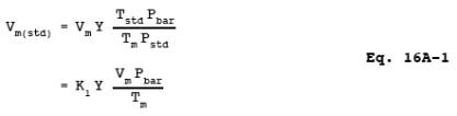
where:
K1 = 0.3855 ˚K/mm Hg for metric units,
= 17.65 ˚R/in. Hg for
English units.
12.3 Concentration of TRS as ppm SO2.
![]()
where:
12.4 Concentration of Recovery Gas Generated in
the System Performance Check.
12.5 Recovery Efficiency for the System Performance Check.
13.0 Method Performance.
13.1 Analytical Range.
The lower detectable
limit is 0.1 ppmv SO2
when sampling at 2 liters/min (4.2
ft3/hr) for 3 hours or 0.3 ppmv when sampling at 2
liters/min (4.2 ft3/hr) for 1 hour. The upper concentration limit
of the method exceeds the TRS levels generally encountered at kraft pulp mills.
13.2 Precision.
Relative standard
deviations of 2.0 and 2.6 percent were obtained when sampling a recovery boiler
for 1 and 3 hours, respectively.
13.3 Bias.
13.3.1 No bias was
found in Method 16A relative to Method 16 in a separate study at a recovery
boiler. 13.3.2 Comparison of Method 16A with Method 16 at a lime kiln indicated
that there was no bias in Method 16A. However, instability of the source
emissions adversely affected the comparison. The precision of Method 16A at the
lime kiln was similar to that obtained at the recovery boiler (Section 13.2.1).
13.3.3 Relative
standard deviations of 2.7 and 7.7 percent have been obtained for system
performance checks.
14.0 Pollution Prevention. [Reserved]
15.0 Waste Management. [Reserved]
16.0 Alternative Procedures.
As an alternative to the
procedures specified in Section 7.1.4, the following procedure may be used to
verify the H2S concentration of the recovery check gas.
16.1 Summary.
The H2S is collected from the calibration gas cylinder and is absorbed in
zinc acetate solution to form zinc sulfide. The latter compound is then
measured iodometrically.
16.2 Range.
The procedure has
been examined in the range of 5 to 1500 ppmv.
16.3 Interferences.
There are no known
interferences to this procedure when used to analyze cylinder gases containing
H2S in nitrogen.
16.4 Precision and Bias.
Laboratory tests have
shown a relative standard deviation of less than 3 percent. The procedure
showed no bias when compared to a gas chromatographic method that used
gravimetrically certified permeation tubes for calibration.
16.5 Equipment and Supplies.
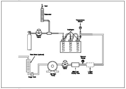
16.5.1 Sampling
Apparatus. The sampling train is shown in Figure 16A-4.
Its component parts are discussed in Sections 16.5.1.1 through 16.5.2.
16.5.1.1 Sampling
Line. Teflon tubing (1/4-in.) to connect the cylinder regulator to the sampling
valve.
16.5.1.2 Needle
Valve. Stainless steel or Teflon needle valve to control the flow rate of gases
to the impingers.
16.5.1.3 Impingers.
Three impingers of approximately 100-ml capacity, constructed to permit the
addition of reagents through the gas inlet stem. The impingers shall be
connected in series with leak-free glass or Teflon connectors. The impinger
bottoms have a standard 24/25 ground-glass fitting. The stems are from standard
6.4-mm (1/4-in.) ball joint midget impingers, custom lengthened by about 1 in.
When fitted together, the stem end should be approximately 1.27 cm (1/2 in.)
from the bottom (Southern Scientific, Inc., Micanopy, Florida: Set Number
S6962-048). The third in-line impinger acts as a drop-out bottle.
16.5.1.4 Drying Tube,
Rate Meter, and Barometer. Same as Method 11,
Sections 6.1.5, 6.1.8, and 6.1.10, respectively.
16.5.1.5 Cylinder Gas
Regulator. Stainless steel, to reduce the pressure of the gas stream entering
the Teflon sampling line to a safe level.
16.5.1.6 Soap Bubble
Meter. Calibrated for 100 and 500 ml, or two separate bubble meters.
16.5.1.7 Critical Orifice.
For volume and rate measurements. The critical orifice may be fabricated
according to Section 16.7.3 and must be calibrated
as specified in Section 16.12.4.
16.5.1.8 Graduated
Cylinder. 50-ml size.
16.5.1.9 Volumetric
Flask. 1-liter size.
16.5.1.10 Volumetric
Pipette. 15-ml size.
16.5.1.11 Vacuum
Gauge. Minimum 20 in. Hg capacity.
16.5.1.12 Stopwatch.
16.5.2 Sample
Recovery and Analysis.
16.5.2.1 Erlenmeyer
Flasks. 125- and 250-ml sizes.
16.5.2.2 Pipettes.
2-, 10-, 20-, and 100-ml volumetric.
16.5.2.3 Burette.
50-ml size.
16.5.2.4 Volumetric
Flask. 1-liter size.
16.5.2.5 Graduated
Cylinder. 50-ml size.
16.5.2.6 Wash Bottle.
16.5.2.7 Stirring
Plate and Bars.
16.6 Reagents and Standards.
Unless otherwise
indicated, all reagents must conform to the specifications established by the
Committee on Analytical Reagents of the American Chemical Society, where such
specifications are available. Otherwise, use the best available grade.
16.6.1 Water. Same as
Method 11, Section 7.1.3.
16.6.2 Zinc Acetate
Absorbing Solution. Dissolve 20 g zinc acetate in water, and dilute to 1 liter.
16.6.3 Potassium
Bi-iodate [KH(IO3)2] Solution, Standard
0.100 N. Dissolve 3.249 g anhydrous KH(IO3)2 in water, and dilute to 1 liter.
16.6.4 Sodium
Thiosulfate (Na2S2O3) Solution, Standard 0.1 N. Same as Method
11, Section 7.3.2. Standardize according to Section 16.12.2.
16.6.5 Na2S2O3 Solution, Standard
0.01 N. Pipette 100.0 ml of 0.1 N Na2S2O3 solution into a 1-liter volumetric flask, and
dilute to the mark with water.
16.6.6 Iodine
Solution, 0.1 N. Same as Method 11, Section 7.2.3.
16.6.7 Standard Iodine
Solution, 0.01 N. Same as in Method 11, Section 7.2.4. Standardize according to
Section 16.12.3.
16.6.8 Hydrochloric
Acid (HCl) Solution, 10 Percent by Weight. Add 230 ml concentrated HCl
(specific gravity 1.19) to 770 ml water.
16.6.9 Starch Indicator
Solution. To 5 g starch (potato, arrowroot, or soluble), add a little cold
water, and grind in a mortar to a thin paste. Pour into 1 liter of boiling
water, stir, and let settle overnight. Use the clear supernatant. Preserve with
1.25 g salicylic acid, 4 g zinc chloride, or a combination of 4 g sodium
propionate and 2 g sodium azide per liter of starch solution. Some commercial
starch substitutes are satisfactory.
16.7 Pre-test Procedures.
16.7.1 Selection of
Gas Sample Volumes. This procedure has been validated for estimating the volume
of cylinder gas sample needed when the H2S
concentration is in the range of 5 to 1500 ppmv. The sample volume ranges were
selected in order to ensure a 35 to 60 percent consumption of the 20 ml of 0.01
N iodine (thus ensuring a 0.01 N Na2S2O3 titer of approximately 7 to 12 ml). The sample
volumes for various H2S concentrations can be estimated by dividing
the approximate ppm-liters desired for a given concentration range by the H2S concentration stated by the manufacturer. For example, for
analyzing a cylinder gas containing approximately 10 ppmv H2S, the optimum sample volume is 65 liters (650 ppm-liters/10 ppmv).
For analyzing a cylinder gas containing approximately 1000 ppmv H2S, the optimum sample volume is 1 liter (1000 ppm-liters/1000
ppmv).
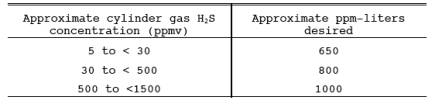
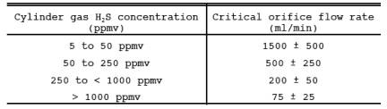
16.7.2 Critical
Orifice Flow Rate Selection. The following table shows the ranges of sample
flow rates that are desirable in order to ensure capture of H2S in the impinger solution. Slight deviations from these ranges
will not have an impact on measured concentrations.
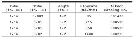
16.7.3
Critical Orifice Fabrication. Critical orifice of desired flow rates may be
fabricated by selecting an orifice tube of desired length and connecting
1/16-in. x 1/4-in. (0.16 cm x 0.64 cm) reducing fittings to both ends. The
inside diameters and lengths of orifice tubes needed to obtain specific flow
rates are shown below.
16.7.4 Determination
of Critical Orifice Approximate Flow Rate. Connect the critical orifice to the
sampling system as shown in Figure 16A-4 but without the H2S cylinder. Connect a rotameter in the line to the first impinger.
Turn on the pump, and adjust the valve to give a reading of about half atmospheric
pressure. Observe the rotameter reading. Slowly increase the vacuum until a
Approximate sampling time ’ Optimum volume Critical orifice flow rate stable
flow rate is reached, and record this as the critical vacuum. The measured flow
rate indicates the expected critical flow rate of the orifice. If this flow
rate is in the range shown in Section 16.7.2, proceed with the critical orifice
calibration according to Section 16.12.4.
16.7.5 Determination
of Approximate Sampling Time. Determine the approximate sampling time for a
cylinder of known concentration. Use the optimum sample volume obtained in
Section 16.7.1.
![]()
16.8 Sample Collection.
16.8.1 Connect the
Teflon tubing, Teflon tee, and rotameter to the flow control needle valve as
shown in Figure 16A-4. Vent the rotameter to an exhaust hood. Plug the open end
of the tee. Five to 10 minutes prior to sampling, open the cylinder valve while
keeping the flow control needle valve closed. Adjust the delivery pressure to
20 psi. Open the needle valve slowly until the rotameter shows a flow rate
approximately 50 to 100 ml above the flow rate of the critical orifice being
used in the system.
16.8.2 Place 50 ml of
zinc acetate solution in two of the impingers, connect them and the empty third
impinger (dropout bottle) and the rest of the equipment as shown in Figure
16A-4. Make sure the ground-glass fittings are tight. The impingers can be
easily stabilized by using a small cardboard box in which three holes have been
cut, to act as a holder. Connect the Teflon sample line to the first impinger.
Cover the impingers with a dark cloth or piece of plastic to protect the
absorbing solution from light during sampling.
16.8.3 Record the
temperature and barometric pressure. Note the gas flow rate through the rotameter.
Open the closed end of the tee. Connect the sampling tube to the tee, ensuring
a tight connection. Start the sampling pump and stopwatch simultaneously. Note
the decrease in flow rate through the excess flow rotameter. This decrease
should equal the known flow rate of the critical orifice being used. Continue
sampling for the period determined in Section 16.7.5.
16.8.4 When sampling
is complete, turn off the pump and stopwatch. Disconnect the sampling line from
the tee and plug it. Close the needle valve followed by the cylinder valve.
Record the sampling time.
16.9 Blank Analysis.
While the sample is
being collected, run a blank as follows: To a 250-ml Erlenmeyer flask, add 100
ml of zinc acetate solution, 20.0 ml of 0.01 N iodine solution, and 2 ml HCl
solution. Titrate, while stirring, with 0.01 N Na2S2O3 until the solution is light yellow. Add starch,
and continue titrating until the blue color disappears. Analyze a blank with
each sample, as the blank titer has been observed to change over the course of
a day.
NOTE: Iodine titration of zinc acetate solutions is
difficult to perform because the solution turns slightly white in color near
the end point, and the disappearance of the blue color is hard to recognize. In
addition, a blue color may reappear in the solution about 30 to 45 seconds
after the titration endpoint is reached. This should not be taken to mean the
original endpoint was in error. It is recommended that persons conducting this
test perform several titrations to be able to correctly identify the endpoint.
The importance of this should be recognized because the results of this
analytical procedure are extremely sensitive to errors in titration.
16.10 Sample Analysis.
Sample treatment is
similar to the blank treatment. Before detaching the stems from the bottoms of
the impingers, add 20.0 ml of 0.01 N iodine solution through the stems of the
impingers holding the zinc acetate solution, dividing it between the two (add
about 15 ml to the first impinger and the rest to the second). Add 2 ml HCl
solution through the stems, dividing it as with the iodine. Disconnect the
sampling line, and store the impingers for 30 minutes. At the end of 30
minutes, rinse the impinger stems into the impinger bottoms. Titrate the
impinger contents with 0.01 N Na2S2O3. Do not transfer the contents of the impinger
to a flask because this may result in a loss of iodine and cause a positive
bias.
16.11 Post-test Orifice Calibration.
Conduct a post-test
critical orifice calibration run using the calibration procedures outlined in
Section 16.12.4. If the Qstd
obtained before and after the test
differs by more than 5 percent, void the sample; if not, proceed to perform the
calculations.
16.12 Calibrations and Standardizations.
16.12.1 Rotameter and
Barometer. Same as Method 11, Sections 10.1.3
and 10.1.4.
16.12.2 Na2S2O3 Solution, 0.1 N.
Standardize the 0.1 N Na2S2O3 solution as follows: To 80 ml water, stirring constantly, add 1 ml
concentrated H2SO4, 10.0 ml
of 0.100 N KH(IO3)2 and 1 g potassium
iodide. Titrate immediately with
0.1 N Na2S2O3 until the solution is light yellow. Add 3 ml starch solution, and
titrate until the blue color just disappears. Repeat the titration until
replicate analyses agree within 0.05 ml. Take the average volume of Na2S2O3 consumed to calculate
the normality to three decimal figures using Equation
16A-5.
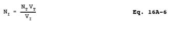
16.12.3 Iodine Solution,
0.01 N. Standardize the 0.01 N iodine solution as follows: Pipet 20.0 ml of
0.01 N iodine solution into a 125-ml Erlenmeyer flask. Titrate with standard
0.01 N Na2S2O3 solution until the solution is light yellow. Add 3 ml starch
solution, and continue titrating until the blue color just disappears. If the
normality of the iodine tested is not 0.010, add a few ml of 0.1 N iodine
solution if it is low, or a few ml of water if it is high, and standardize
again. Repeat the titration until replicate values agree within 0.05 ml. Take
the average volume to calculate the normality to three decimal figures using
Equation 16A-6.
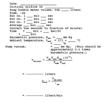
16.12.4 Critical Orifice. Calibrate the critical orifice using the
sampling train shown in Figure 16A-4 but without the H2S cylinder and vent rotameter. Connect the soap bubble meter to the
Teflon line that is connected to the first impinger. Turn on the pump, and
adjust the needle valve until the vacuum is higher than the critical vacuum
determined in Section 16.7.4. Record the time required for gas flow to equal
the soap bubble meter volume (use the 100-ml soap bubble meter for gas flow
rates below 100 ml/min, otherwise use the 500-ml soap bubble meter). Make three
runs, and record the data listed in Table 16A-1. Use
these data to calculate the volumetric flow rate of the orifice.
16.13 Calculations.
16.13.1 Nomenclature.
Bwa = Fraction of water vapor in ambient air during
orifice calibration.
CH2S = H2S concentration in cylinder gas, ppmv.
Ma = Molecular weight of ambient air saturated at impinger
temperature, g/g-mole.
Ms = Molecular weight of sample gas (nitrogen) saturated at impinger
temperature, g/g-mole.
NOTE: (For tests carried out in a laboratory where the
impinger temperature is 25 ˚C, Ma = 28.5 g/g-mole and Ms = 27.7 g/g-mole.)
NI = Normality of standard iodine solution (0.01 N), g-eq/liter.
NT = Normality of standard Na2S2O3 solution (0.01 N), g-eq/liter.
Pbar = Barometric pressure, mm Hg.
Pstd = Standard absolute pressure, 760 mm Hg.
¯Qstd = Average volumetric flow rate through critical
orifice, liters/min.
Tamb = Absolute ambient temperature, ˚K.
Tstd = Standard absolute temperature, 293 ˚K.
Os = Sampling time, min.
Osb = Time for soap bubble meter flow rate
measurement, min.
Vm(std) = Sample gas volume measured by the critical
orifice, corrected to standard conditions, liters.
Vsb = Volume of gas as measured by the soap bubble
meter, ml.
Vsb(std)= Volume of gas as measured by the soap bubble
meter, corrected to standard conditions, liters.
VI = Volume of standard iodine solution (0.01 N) used, ml.
VT = Volume of standard Na2S2O3 solution (0.01 N) used, ml.
VTB = Volume of standard Na2S2O3 solution (0.01 N)
used for the blank, ml.
16.13.2 Normality of Standard Na2S2O3 Solution (0.1 N).
![]()
16.13.3 Normality of
Standard Iodine Solution (0.01 N).
16.13.4 Sample Gas
Volume.
![]()
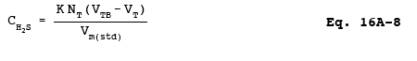
16.13.5 Concentration
of H2S in the Gas Cylinder.
17.0 References.
1. American Public Health
Association, American Water Works Association, and Water Pollution Control
Federation. Standard Methods for the Examination of Water and Wastewater.
Washington, DC. American Public Health Association. 1975. pp. 316-317.
2. American Society
for Testing and Materials. Annual Book of ASTM Standards. Part 31: Water,
Atmospheric Analysis. Philadelphia, PA. 1974. pp. 40-42.
3. Blosser, R.O. A
Study of TRS Measurement Methods. National Council of the Paper Industry for
Air and Stream Improvement, Inc., New York, NY. Technical Bulletin No. 434. May
1984. 14 pp.
4. Blosser, R.O.,
H.S. Oglesby, and A.K. Jain. A Study of Alternate SO2 Scrubber Designs Used for TRS Monitoring. A Special Report by the
National Council of the Paper Industry for Air and Stream Improvement, Inc.,
New York, NY. July 1977.
5. Curtis, F., and
G.D. McAlister. Development and Evaluation of an Oxidation/Method 6 TRS
Emission Sampling Procedure. Emission Measurement Branch, Emission Standards
and Engineering Division, U.S. Environmental Protection Agency, Research
Triangle Park, NC 27711. February 1980.
6. Gellman, I. A
Laboratory and Field Study of Reduced Sulfur Sampling and Monitoring Systems.
National Council of the Paper Industry for Air and Stream Improvement, Inc.,
New York, NY. Atmospheric Quality Improvement Technical Bulletin No. 81.
October 1975.
7. Margeson, J.H.,
J.E. Knoll, and M.R. Midgett. A Manual Method for TRS Determination. Source
Branch, Quality Assurance Division, U.S. Environmental Protection Agency,
Research Triangle Park, NC 27711.
8. National Council
of the Paper Industry for Air and Stream Improvement. An Investigation of H2S and SO2. Calibration Cylinder Gas Stability and Their
Standardization Using Wet Chemical Techniques. Special Report 76-06. New York, NY.
August 1976.
9. National Council
of the Paper Industry for Air and Stream Improvement. Wet Chemical Method for
Determining the H2S Concentration of Calibration Cylinder Gases.
Technical Bulletin Number 450. New York, NY. January 1985. 23 pp.
10. National Council
of the Paper Industry for Air and Stream Improvement. Modified Wet Chemical
Method for Determining the H2S Concentration of
Calibration Cylinder Gases. Draft Report. New York, NY. March 1987. 29 pp.
18.0 Tables, Diagrams, Flowcharts, and Validation Data.
Figure
16A-2. Angled Sampling Probe.
Figure
16A-3. Recovery Gas Dilution System.
Figure
16A-4. Recovery Check Gas Sampling Train.
Table
16A-1. Critical Orifice Calibration Data.