METHOD 10B -
DETERMINATION OF CARBON MONOXIDE EMISSIONS FROM STATIONARY SOURCES
NOTE: This method is not inclusive with respect to
specifications (e.g., equipment
and supplies) and procedures (e.g.,
sampling and analytical) essential to its performance. Some material is
incorporated by reference from other methods in this part. Therefore, to obtain
reliable results, persons using this method should have a thorough knowledge of
at least the following additional test methods: Method
1, Method 4, Method
10A, and Method 25.
8.0 Sample Collection,
Preservation, Storage, and Transport.
10.0 Calibration and
Standardization.
10.2 Reduction Catalyst
Efficiency Check.
11.1 Preparation for
Analysis.
12.0 Calculations and Data
Analysis.
13.0 Method
Performance. [Reserved]
14.0 Pollution
Prevention. [Reserved]
15.0 Waste Management.
[Reserved]
17.0 Tables, Diagrams,
Flowcharts, and Validation Data. [Reserved]
1.0 Scope and Application.
1.1 Analytes.
![]()
1.2 Applicability.
This method applies
to the measurement of CO emissions at petroleum refineries and from other
sources when specified in an applicable subpart of the regulations.
1.3 Data Quality Objectives.
Adherence to the
requirements of this method will enhance the quality of the data obtained from
air pollutant sampling methods.
2.0 Summary of Method.
2.1 An integrated gas
sample is extracted from the sampling point, passed through a conditioning system
to remove interferences, and collected in a Tedlar bag. The CO is separated
from the sample by gas chromatography (GC) and catalytically reduced to methane
(CH4) which is determined by flame ionization
detection (FID). The analytical portion of this method is identical to
applicable sections in Method 25 detailing CO measurement.
3.0 Definitions. [Reserved]
4.0 Interferences.
4.1 Carbon dioxide
(CO2) and organics potentially can interfere with
the analysis. Most of the CO2 is removed from the sample
by the alkaline permanganate conditioning system; any residual CO2 and organics are separated from the CO by GC.
5.0 Safety.
5.1 Disclaimer.
This method may
involve hazardous materials, operations, and equipment. This test method may
not address all of the safety problems associated with its use. It is the
responsibility of the user of this test method to establish appropriate safety
and health practices and determine the applicability of regulatory limitations
prior to performing this test method. The analyzer users manual should be
consulted for specific precautions concerning the analytical procedure.
6.0 Equipment and Supplies.
6.1 Sample Collection.
Same as in Method 10A, Section 6.1.
6.2 Sample Analysis.
A GC/FID analyzer,
capable of quantifying CO in the sample and consisting of at least the
following major components, is required for sample analysis. [Alternatively,
complete Method 25 analytical systems (Method 25,
Section 6.3) are acceptable alternatives when calibrated for CO and
operated in accordance with the Method 25 analytical procedures (Method 25, Section 11.0).]
6.2.1 Separation
Column. A column capable of separating CO from CO2 and
organic compounds that may be present. A 3.2-mm (c-in.) OD stainless steel
column packed with 1.7 m (5.5 ft.) of 60/80 mesh Carbosieve S-II (available
from Supelco) has been used successfully for this purpose.
6.2.2 Reduction Catalyst.
Same as in Method 25, Section 6.3.1.2.
6.2.3 Sample
Injection System. Same as in Method 25, Section 6.3.1.4, equipped to accept a
sample line from the Tedlar bag.
6.2.4 Flame
Ionization Detector. Meeting the linearity specifications of Section 10.3 and
having a minimal instrument range of 10 to 1,000 ppm CO.
6.2.5 Data Recording
System. Analog strip chart recorder or digital integration system, compatible
with the FID, for permanently recording the analytical results.
7.0 Reagents and Standards.
7.1 Sample Collection.
Same as in Method 10A, Section 7.1.
7.2 Sample Analysis.
7.2.1 Carrier, Fuel,
and Combustion Gases. Same as in Method 25,
Sections 7.2.1, 7.2.2, and 7.2.3, respectively.
7.2.2
Calibration Gases. Three standard gases with nominal CO concentrations of 20,
200, and 1,000 ppm CO in nitrogen. The calibration gases shall be certified by
the manufacturer to be ± 2 percent of the specified concentrations.
7.2.3 Reduction
Catalyst Efficiency Check Calibration Gas. Standard CH4 gas with a nominal concentration of 1,000 ppm in air.
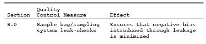
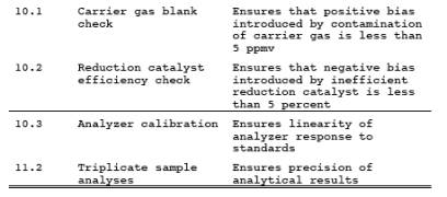
8.0 Sample Collection, Preservation, Storage, and Transport.
Same as in Method 10A, Section 8.0.
9.0 Quality Control.
10.0 Calibration and Standardization.
10.1 Carrier Gas Blank Check.
Analyze each new tank
of carrier gas with the GC analyzer according to Section11.2 to check for
contamination. The corresponding
concentration must be less than 5 ppm for the tank to be acceptable for use.
10.2 Reduction Catalyst Efficiency Check.
Prior to initial use,
the reduction catalyst shall be tested for reduction efficiency. With the
heated reduction catalyst bypassed, make triplicate injections of the 1,000 ppm
CH4 gas (Section 7.2.3) to calibrate the analyzer.
Repeat the procedure using 1,000 ppm CO gas (Section
7.2.2) with the catalyst in operation. The reduction catalyst operation is
acceptable if the CO response is within 5 percent of the certified gas value.
10.3 Analyzer Calibration.
Perform this test
before the system is first placed into operation. With the reduction catalyst
in operation, conduct a linearity check of the analyzer using the standards
specified in Section 7.2.2. Make triplicate injections of each calibration gas,
and then calculate the average response factor (area/ppm) for each gas, as well
as the overall mean of the response factor values. The instrument linearity is
acceptable if the average response factor of each calibration gas is within 2.5
percent of the overall mean value and if the relative standard deviation
(calculated in Section 12.8 of Method 25) for each set of triplicate injections
is less than 2 percent. Record the overall mean of the response factor values
as the calibration response factor (R).
11.0 Analytical Procedure.
11.1 Preparation for Analysis.
Before putting the GC
analyzer into routine operation, conduct the calibration procedures listed in
Section 10.0. Establish an appropriate carrier flow rate and detector
temperature for the specific instrument used.
11.2 Sample Analysis.
Purge the sample loop
with sample, and then inject the sample. Analyze each sample in triplicate, and
calculate the average sample area (A). Determine the bag CO concentration
according to Section 12.2.
12.0 Calculations and Data Analysis.
Carry out
calculations retaining at least one extra significant figure beyond that of the
acquired data. Round off results only after the final calculation.
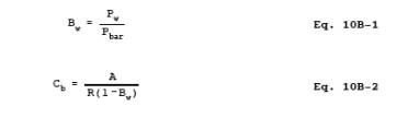
12.1 Nomenclature.
A = Average sample
area.
Bw = Moisture content in the bag sample, fraction.
C = CO concentration
in the stack gas, dry basis, ppm.
Cb = CO concentration in the bag sample, dry basis, ppm.
F = Volume fraction
of CO2 in the stack, fraction.
Pbar = Barometric pressure, mm Hg.
Pw = Vapor pressure of the H2O in the
bag (from Table 10A-2, Method 10A), mm Hg.
R = Mean calibration
response factor, area/ppm.
12.2 CO Concentration
in the Bag. Calculate Cb
using Equations 10B-1 and 10B-2. If
condensate is visible in the Tedlar bag, calculate Bw using Table 10A-2 of Method 10A and the temperature and barometric
pressure in the analysis room. If condensate is not visible, calculate Bw using the temperature and barometric pressure at the sampling site.
12.3 CO Concentration
in the Stack
![]()
13.0 Method Performance. [Reserved]
14.0 Pollution Prevention. [Reserved]
15.0 Waste Management. [Reserved]
16.0 References.
Same as in Method 25, Section 16.0, with the addition of
the following:
1. Butler, F.E, J.E.
Knoll, and M.R. Midgett. Development and Evaluation of Methods for Determining
Carbon Monoxide Emissions. Quality Assurance Division, Environmental Monitoring
Systems Laboratory, U.S. Environmental Protection Agency, Research Triangle
Park, NC. June 1985. 33 pp.
17.0 Tables, Diagrams, Flowcharts, and Validation Data. [Reserved]