METHOD
10A - DETERMINATION OF CARBON MONOXIDE EMISSIONS IN CERTIFYING CONTINUOUS
EMISSION MONITORING SYSTEMS AT PETROLEUM REFINERIES
NOTE: This method does not include all of the
specifications (e.g.,
equipment and supplies) and procedures (e.g., sampling and analytical) essential to
its performance. Some material is incorporated by reference from other methods
in this part. Therefore, to obtain reliable results, persons using this method
should have a thorough knowledge of at least the following additional test
methods: Method 1, Method 4,
and Method 5.
8.0 Sample Collection,
Preservation, Storage, and Transport.
8.3 Carbon Dioxide
Measurement.
10.0 Calibration and
Standardization.
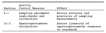
10.3 Spectrophotometer
Calibration Curve.
12.0 Calculations and
Data Analysis.
14.0 Pollution
Prevention. [Reserved]
15.0 Waste Management.
[Reserved]
17.0 Tables, Diagrams,
Flowcharts, and Validation Data.
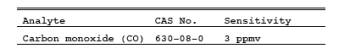
1.0 Scope and Application.
1.1 Analytes.
1.2 Applicability.
This method is
applicable for the determination of CO emissions at petroleum refineries. This
method serves as the reference method in the relative accuracy test for
nondispersive infrared (NDIR) CO continuous emission monitoring systems (CEMS)
that are required to be installed in petroleum refineries on fluid catalytic
cracking unit catalyst regenerators [§ 60.105(a)(2) of this part].
1.3 Data Quality Objectives.
Adherence to
the requirements of this method will enhance the quality of the data obtained
from air pollutant sampling methods.
2.0 Summary of Method.
An integrated
gas sample is extracted from the stack, passed through an alkaline permanganate
solution to remove sulfur oxides and nitrogen oxides, and collected in a Tedlar
bag. The CO concentration in the sample is measured spectrophotometrically
using the reaction of CO with p-sulfaminobenzoic
acid.
3.0 Definitions. [Reserved]
4.0 Interferences.
Sulfur oxides,
nitric oxide, and other acid gases interfere with the colorimetric reaction.
They are removed by passing the sampled gas through an alkaline potassium
permanganate scrubbing solution. Carbon dioxide (CO2) does not interfere, but, because it is
removed by the scrubbing solution, its concentration must be measured
independently and an appropriate volume correction made to the sampled gas.
5.0 Safety.
5.1 Disclaimer.
This method
may involve hazardous materials, operations, and equipment. This test method
may not address all of the safety problems associated with its use. It is the
responsibility of the user of this test method to establish appropriate safety
and health practices and determine the applicability of regulatory limitations
prior to performing this test method. The analyzer users manual should be
consulted for specific precautions to be taken with regard to the analytical
procedure.
5.2 Corrosive reagents.
The following
reagents are hazardous. Personal protective equipment and safe procedures are
useful in preventing chemical splashes. If contact occurs, immediately flush
with copious amounts of water for at least 15 minutes. Remove clothing under
shower and decontaminate. Treat residual chemical burns as thermal burns.
5.2.1 Sodium
Hydroxide (NaOH). Causes severe damage to eyes and skin. Inhalation causes
irritation to nose, throat, and lungs. Reacts exothermically with limited
amounts of water.
6.0 Equipment and Supplies.
6.1 Sample Collection.
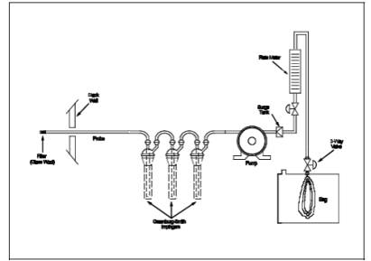
The sampling
train shown in Figure 10A-1 is required for sample
collection. Component parts are described below:
6.1.1 Probe.
Stainless steel, sheathed Pyrex glass, or equivalent, equipped with a glass
wool plug to remove particulate matter.
6.1.2 Sample
Conditioning System. Three Greenburg-Smith impingers connected in series with
leak-free connections.
6.1.3 Pump.
Leak-free pump with stainless steel and Teflon parts to transport sample at a
flow rate of 300 ml/min (0.01 ft3/min) to
the flexible bag.
6.1.4 Surge
Tank. Installed between the pump and the rate meter to eliminate the pulsation
effect of the pump on the rate meter.
6.1.5 Rate
Meter. Rotameter, or equivalent, to measure flow rate at 300 ml/min (0.01 ft3/min). Calibrate according to Section
10.2.
6.1.6 Flexible
Bag. Tedlar, or equivalent, with a capacity of 10 liters (0.35 ft3) and equipped with a sealing
quick-connect plug. The bag must be leak-free according to Section
8.1. For protection, it is recommended that the bag be enclosed within a
rigid container.
6.1.7 Valves.
Stainless-steel needle valve to adjust flow rate, and stainless-steel three-way
valve, or equivalent.
6.1.8 CO2 Analyzer. Fyrite, or equivalent, to
measure CO2 concentration to within O.5 percent.
6.1.9 Volume
Meter. Dry gas meter, capable of measuring the sample volume under calibration
conditions of 300 ml/min (0.01 ft3/min)
for 10 minutes.
6.1.10
Pressure Gauge. A water filled U-tube manometer, or equivalent, of about 30 cm
(12 in.) to leak-check the flexible bag.
6.2 Sample Analysis.
6.2.1
Spectrophotometer. Single- or double-beam to measure absorbance at 425 and 600
nm. Slit width should not exceed 20 nm.
6.2.2 Spectrophotometer
Cells. 1-cm pathlength.
6.2.3 Vacuum
Gauge. U-tube mercury manometer, 1 meter (39 in.), with 1-mm divisions, or
other gauge capable of measuring pressure to within 1 mm Hg.
6.2.4 Pump.
Capable of evacuating the gas reaction bulb to a pressure equal to or less than
40 mm Hg absolute, equipped with coarse and fine flow control valves.
6.2.5
Barometer. Mercury, aneroid, or other barometer capable of measuring
atmospheric pressure to within 1 mm Hg.
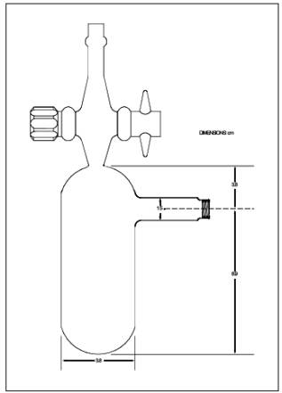
6.2.6 Reaction
Bulbs. Pyrex glass, 100-ml with Teflon stopcock (Figure
10A-2), leak-free at 40 mm Hg, designed so that 10 ml of the colorimetric
reagent can be added and removed easily and accurately. Commercially available
gas sample bulbs such as Supelco Catalog No. 2-2161 may also be used.
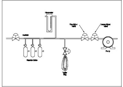
6.2.7
Manifold. Stainless steel, with connections for three reaction bulbs and the
appropriate connections for the manometer and sampling bag as shown in Figure 10A-3.
6.2.8 Pipets.
Class A, 10-ml size.
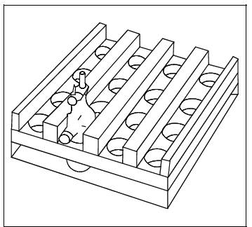
6.2.9 Shaker
Table. Reciprocating-stroke type such as Eberbach Corporation, Model 6015. A
rocking arm or rotary-motion type shaker may also be used. The shaker must be
large enough to accommodate at least six gas sample bulbs simultaneously. It
may be necessary to construct a tabletop extension for most commercial shakers
to provide sufficient space for the needed bulbs (Figure
10A-4).
6.2.10 Valve.
Stainless steel shut-off valve.
6.2.11
Analytical Balance. Capable of weighing to 0.1 mg.
7.0 Reagents and Standards.
Unless
otherwise indicated, all reagents shall conform to the specifications
established by the Committee on Analytical Reagents of the American Chemical
Society, where such specifications are available; otherwise, the best available
grade shall be used.
7.1 Sample Collection.
7.1.1 Water.
Deionized distilled, to conform to ASTM D 1193-77 or 91, Type 3 (incorporated
by reference--see § 60.17). If high concentrations of organic matter are not
expected to be present, the potassium permanganate test for oxidizable organic
matter may be omitted.
7.1.2 Alkaline
Permanganate Solution, 0.25 M KMnO4/1.5
M Sodium Hydroxide (NaOH). Dissolve 40 g KMnO4 and
60 g NaOH in approximately 900 ml water, cool, and dilute to 1 liter.
7.2 Sample Analysis
7.2.1 Water.
Same as in Section 7.1.1.
7.2.2 1 M
Sodium Hydroxide Solution. Dissolve 40 g NaOH in approximately 900 ml of water,
cool, and dilute to 1 liter.
7.2.3 0.1 M
NaOH Solution. Dilute 50 ml of the 1 M NaOH solution prepared in Section 7.2.2
to 500 ml.
7.2.4 0.1 M
Silver Nitrate (AgNO3) Solution. Dissolve 8.5 g AgNO3 in water, and dilute to 500 ml.
7.2.5 0.1 M
Para-Sulfaminobenzoic Acid (p-SABA) Solution. Dissolve 10.0 g p-SABA in 0.1 M
NaOH, and dilute to 500 ml with 0.1 M NaOH.
7.2.6
Colorimetric Solution. To a flask, add 100 ml of 0.1 M p-SABA solution and 100
ml of 0.1 M AgNO3
solution. Mix, and add 50 ml
of 1 M NaOH with shaking. The resultant solution should be clear and colorless.
This solution is acceptable for use for a period of 2 days.
7.2.7 Standard
Gas Mixtures. Traceable to National Institute of Standards and Technology
(NIST) standards and containing between 50 and 1000 ppm CO in nitrogen. At
least two concentrations are needed to span each calibration range used
(Section 10.3). The calibration gases must be certified by the manufacturer to
be within 2 percent of the specified concentrations.
8.0 Sample Collection, Preservation, Storage, and Transport.
8.1 Sample Bag Leak-Checks.
While a bag
leak-check is required after bag use, it should also be done before the bag is
used for sample collection. The bag should be leak-checked in the inflated and
deflated condition according to the following procedure:
8.1.1 Connect
the bag to a water manometer, and pressurize the bag to 5 to 10 cm H2O (2 to 4 in H2O). Allow the bag to stand for 60
minutes. Any displacement in the water manometer indicates a leak.
8.1.2 Evacuate
the bag with a leakless pump that is connected to the downstream side of a flow
indicating device such as a 0- to 100-ml/min rotameter or an impinger
containing water. When the bag is completely evacuated, no flow should be
evident if the bag is leak-free.
8.2 Sample Collection.
8.2.1 Evacuate
the Tedlar bag completely using a vacuum pump. Assemble the apparatus as shown
in Figure 10A-1. Loosely pack glass wool in the tip of the probe. Place 400 ml
of alkaline permanganate solution in the first two impingers and 250 ml in the
third. Connect the pump to the third impinger, and follow this with the surge
tank, rate meter, and 3-way valve. Do not connect the Tedlar bag to the system
at this time.
8.2.2
Leak-check the sampling system by plugging the probe inlet, opening the 3-way
valve, and pulling a vacuum of approximately 250 mm Hg on the system while
observing the rate meter for flow. If flow is indicated on the rate meter, do
not proceed further until the leak is found and corrected.
8.2.3 Purge
the system with sample gas by inserting the probe into the stack and drawing
the sample gas through the system at 300 ml/min ± 10 percent for 5 minutes.
Connect the evacuated Tedlar bag to the system, record the starting time, and
sample at a rate of 300 ml/min for 30 minutes, or until the Tedlar bag is
nearly full. Record the sampling time, the barometric pressure, and the ambient
temperature. Purge the system as
described above immediately before each sample.
8.2.4 The
scrubbing solution is adequate for removing sulfur oxides and nitrogen oxides
from 50 liters (1.8 ft3) of stack gas when the concentration of
each is less than 1,000 ppm and the CO2 concentration
is less than 15 percent. Replace
the scrubber solution after every fifth sample.
8.3 Carbon Dioxide Measurement.
Measure the CO2 content in the stack to the nearest 0.5
percent each time a CO sample is collected. A simultaneous grab sample analyzed
by the Fyrite analyzer is acceptable.
9.0 Quality Control.
9.1
Miscellaneous Quality Control Measures.
9.2 Volume
Metering System Checks. Same as Method 5, Section
9.2.
10.0 Calibration and Standardization.
NOTE: Maintain a laboratory log of all
calibrations.
10.1 Gas Bulb Calibration.
Weigh the
empty bulb to the nearest 0.1 g. Fill the bulb to the stopcock with water, and
again weigh to the nearest 0.1 g. Subtract the tare weight, and calculate the
volume in liters to three significant figures using the density of water at the
measurement temperature. Record the volume on the bulb. Alternatively, mark an identification
number on the bulb, and record the volume in a notebook.
10.2 Rate Meter Calibration.
Assemble the
system as shown in Figure 10A-1 (the impingers may be removed), and attach a
volume meter to the probe inlet. Set the rotameter at 300 ml/min, record the
volume meter reading, start the pump, and pull ambient air through the system
for 10 minutes. Record the final volume meter reading. Repeat the procedure and
average the results to determine the volume of gas that passed through the
system.
10.3 Spectrophotometer Calibration Curve.
10.3.1 Collect
the standards as described in Section 8.2. Prepare at
least two sets of three bulbs as standards to span the 0 to 400 or 400 to 1000
ppm range. If any samples span both concentration ranges, prepare a calibration
curve for each range using separate reagent blanks. Prepare a set of three
bulbs containing colorimetric reagent but no CO to serve as a reagent
blank. Analyze each standard and
blank according to the sample analysis procedure of Section 11.0 Reject the
standard set where any of the individual bulb absorbances differs from the set
mean by more than 10 percent.
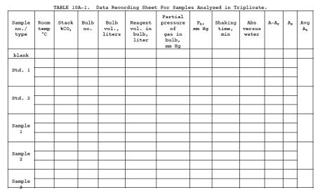
10.3.2
Calculate the average absorbance for each set (3 bulbs) of standards using Equation 10A-1 and Table 10A-1.
Construct a graph of average absorbance for each standard against its
corresponding concentration. Draw a smooth curve through the points. The curve
should be linear over the two concentration ranges discussed in Section 13.3.
11.0 Analytical Procedure.
11.1 Assemble
the system shown in Figure 10A-3, and record the information required in Table
10A-1 as it is obtained. Pipet 10.0 ml of the colorimetric reagent into each
gas reaction bulb, and attach the bulbs to the system. Open the stopcocks to the reaction
bulbs, but leave the valve to the Tedlar bag closed. Turn on the pump, fully
open the coarse-adjust flow valve, and slowly open the fine-adjust valve until
the pressure is reduced to at least 40 mm Hg. Now close the coarse adjust
valve, and observe the manometer to be certain that the system is leak-free.
Wait a minimum of 2 minutes. If the pressure has increased less than 1 mm Hg,
proceed as described below. If a leak is present, find and correct it before
proceeding further.
11.2 Record
the vacuum pressure (Pv) to the nearest 1 mm Hg, and close the
reaction bulb stopcocks. Open the Tedlar bag valve, and allow the system to
come to atmospheric pressure. Close the bag valve, open the pump coarse adjust
valve, and evacuate the system again. Repeat this fill/evacuation procedure at
least twice to flush the manifold completely. Close the pump coarse adjust
valve, open the Tedlar bag valve, and let the system fill to atmospheric
pressure. Open the stopcocks to the reaction bulbs, and let the entire system
come to atmospheric pressure. Close the bulb stopcocks, remove the bulbs,
record the room temperature and barometric pressure (Pbar, to nearest mm Hg), and place the bulbs
on the shaker table with their main axis either parallel to or perpendicular to
the plane of the table top. Purge the bulb-filling system with ambient air for
several minutes between samples. Shake the samples for exactly 2 hours.
11.3
Immediately after shaking, measure the absorbance (A) of each bulb sample at
425 nm if the concentration is less than or equal to 400 ppm CO or at 600 nm if
the concentration is above 400 ppm.
NOTE: This may be accomplished with multiple
bulb sets by sequentially collecting sets and adding to the shaker at staggered
intervals, followed by sequentially removing sets from the shaker for
absorbance measurement after the two-hour designated intervals have elapsed.
11.4 Use a
small portion of the sample to rinse a spectrophotometer cell several times
before taking an aliquot for analysis. If one cell is used to analyze multiple
samples, rinse the cell with deionized distilled water several times between
samples. Prepare and analyze standards and a reagent blank as described in
Section 10.3. Use water as the reference. Reject the analysis if the blank
absorbance is greater than 0.1. All conditions should be the same for analysis
of samples and standards. Measure the absorbances as soon as possible after
shaking is completed.
11.5 Determine
the CO concentration of each bag sample using the calibration curve for the
appropriate concentration range as discussed in Section 10.3.
12.0 Calculations and Data Analysis.
Carry out
calculations retaining at least one extra decimal figure beyond that of the
acquired data. Round off figures after final calculation.
12.1
Nomenclature.
A = Sample
absorbance, uncorrected for the reagent blank.
Ar = Absorbance of the reagent blank.
As = Average sample absorbance per liter,
units/liter.
Bw = Moisture content in the bag sample.
C = CO
concentration in the stack gas, dry basis, ppm.
Cb = CO concentration of the bag sample, dry
basis, ppm.
Cg = CO concentration from the calibration
curve, ppm.
F = Volume
fraction of CO2
in the stack.
n = Number of
reaction bulbs used per bag sample.
Pb = Barometric pressure, mm Hg.
Pv = Residual pressure in the sample bulb after
evacuation, mm Hg.
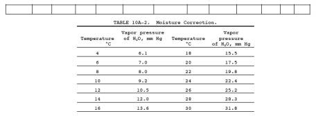
Pw = Vapor pressure of H2O in the bag (from Table 10A-2), mm Hg.
Vb = Volume of the sample bulb, liters.
Vr = Volume of reagent added to the sample
bulb, 0.0100 liter.
12.2
Average Sample Absorbance per Liter. Calculate As for
each gas bulb using Equation 10A-1, and record the value in Table 10A-1.
Calculate the average As
for each bag sample, and
compare the three values to the average. If any single value differs by more
than 10 percent from the average, reject this value, and calculate a new
average using the two remaining values.
![]()
NOTE: A and Ar must
be at the same wavelength.
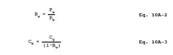
12.3 CO
Concentration in the Bag. Calculate Cb using
Equations 10A-2 and 10A-3. If condensate is visible in the Tedlar bag,
calculate Bw
using Table
10A-2 and the temperature and barometric pressure in the analysis room. If
condensate is not visible, calculate Bw using
the temperature and barometric pressure at the sampling site.
12.4 CO
Concentration in the Stack.
![]()
13.0 Method Performance.
13.1 Precision.
The estimated
intralaboratory standard deviation of the method is 3 percent of the mean for
gas samples analyzed in duplicate in the concentration range of 39 to 412 ppm.
The interlaboratory precision has not been established.
13.2 Accuracy.
The method
contains no significant biases when compared to an NDIR analyzer calibrated
with NIST standards.
13.3 Range.
Approximately
3 to 1800 ppm CO. Samples having concentrations below 400 ppm are analyzed at
425 nm, and samples having concentrations above 400 ppm are analyzed at 600 nm.
13.4 Sensitivity.
The detection
limit is 3 ppmv based on a change in concentration equal to three times the
standard deviation of the reagent blank solution.
13.5 Stability.
The individual
components of the colorimetric reagent are stable for at least 1 month. The
colorimetric reagent must be used within 2 days after preparation to avoid
excessive blank correction. The samples in the Tedlar bag should be stable for
at least 1 week if the bags are leak-free.
14.0 Pollution Prevention. [Reserved]
15.0 Waste Management. [Reserved]
16.0 References.
1. Butler,
F.E., J.E. Knoll, and M.R. Midgett. Development and Evaluation of Methods for
Determining Carbon Monoxide Emissions. U.S. Environmental Protection Agency,
Research Triangle Park, N.C. June 1985. 33 pp.
2. Ferguson,
B. B., R.E. Lester, and W.J. Mitchell. Field Evaluation of Carbon Monoxide and
Hydrogen Sulfide Continuous Emission Monitors at an Oil Refinery. U.S.
Environmental Protection Agency, Research Triangle Park, N.C. Publication No.
EPA-600/4-82-054. August 1982. 100 pp.
3. Lambert,
J.L., and R.E. Weins. Induced Colorimetric Method for Carbon Monoxide.
Analytical Chemistry. 46(7):929-930. June 1974.
4. Levaggi, D.A.,
and M. Feldstein. The Colorimetric Determination of Low Concentrations of
Carbon Monoxide. Industrial Hygiene Journal. 25:64-66. January-February 1964.
5. Repp, M.
Evaluation of Continuous Monitors For Carbon Monoxide in Stationary Sources.
U.S. Environmental Protection Agency. Research Triangle Park, N.C. Publication
No. EPA-600/2-77-063. March 1977. 155 pp.
6. Smith, F.,
D.E. Wagoner, and R.P. Donovan. Guidelines for Development of a Quality
Assurance Program: Volume VIII - Determination of CO Emissions from Stationary
Sources by NDIR Spectrometry. U.S. Environmental Protection Agency. Research
Triangle Park, N.C. Publication No. EPA- 650/4-74-005-h. February 1975. 96 pp.
17.0 Tables, Diagrams, Flowcharts, and Validation
Data.
Figure
10A-2. Sample Reaction Bulbs.
Figure
10A-3. Sample Bulb Filling System.
Figure
10A-4. Shaker Table Adapter.