METHOD 4 - DETERMINATION OF MOISTURE CONTENT IN STACK GASES
NOTE: This method does not include all the
specifications (e.g.,
equipment and supplies) and procedures (e.g., sampling) essential to its performance. Some
material is incorporated by reference from other methods in this part.
Therefore, to obtain reliable results, persons using this method should have a
thorough knowledge of at least the following additional test methods: Method 1, Method 5, and Method 6.
6.1.5 Barometer and
Graduated Cylinder and/or Balance.
6.2.9 Graduated
Cylinder. 25-ml.
7.0 Reagents and
Standards. [Reserved]
8.0 Sample Collection,
Preservation, Transport, and Storage.
8.1.1 Preliminary
Determinations.
8.1.2 Preparation of
Sampling Train.
8.1.4 Sampling Train
Operation.
10.0 Calibration and
Standardization.
12.0 Data Analysis and
Calculations.
12.1.2 Volume of Water
Vapor Condensed.
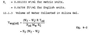
12.1.3 Volume of Water Collected in Silica Gel
12.1.6 Verification of
Constant Sampling Rate.
12.1.7 In saturated or
moisture droplet-laden gas streams
12.2.2 Volume of Water
Vapor Collected.
12.2.4 Approximate
Moisture Content.
13.0 Method
Performance. [Reserved]
14.0 Pollution
Prevention. [Reserved]
15.0 Waste Management.
[Reserved]
18.0 Tables, Diagrams,
Flowcharts, and Validation Data.
1.0 Scope and Application.
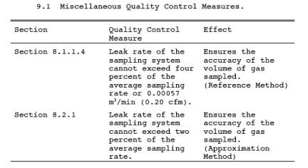
1.1 Analytes.
1.2 Applicability.
This method is
applicable for the determination of the moisture content of stack gas.
1.3 Data Quality Objectives.
Adherence to the
requirements of this method will enhance the quality of the data obtained from
air pollutant sampling methods.
2.0 Summary of Method.
2.1 A gas sample is
extracted at a constant rate from the source; moisture is removed from the
sample stream and determined either volumetrically or gravimetrically.
2.2 The method
contains two possible procedures: a reference method and an approximation
method.
2.2.1 The reference
method is used for accurate determinations of moisture content (such as are
needed to calculate emission data). The approximation method, provides
estimates of percent moisture to aid in setting isokinetic sampling rates prior
to a pollutant emission measurement run. The approximation method described
herein is only a suggested approach; alternative means for approximating the
moisture content (e.g.,
drying tubes, wet bulb-dry bulb techniques, condensation techniques,
stoichiometric calculations, previous experience, etc.) are also acceptable.
2.2.2 The reference
method is often conducted simultaneously with a pollutant emission measurement
run. When it is, calculation of percent isokinetic, pollutant emission rate,
etc., for the run shall be based upon the results of the reference method or
its equivalent. These calculations shall not be based upon the results of the
approximation method, unless the approximation method is shown, to the
satisfaction of the Administrator, to be
capable of yielding
results within one percent H2O of the reference
method.
3.0 Definitions. [Reserved]
4.0 Interferences.
4.1 The moisture
content of saturated gas streams or streams that contain water droplets, as
measured by the reference method, may be positively biased. Therefore, when
these conditions exist or are suspected, a second determination of the moisture
content shall be made simultaneously with the reference method, as
follows: Assume that the gas
stream is saturated. Attach a temperature sensor [capable of measuring to ±1 °C
(2 °F)] to the reference method probe. Measure the stack gas temperature at
each traverse point (see Section 8.1.1.1) during the
reference method traverse, and calculate the average stack gas temperature.
Next, determine the moisture percentage, either by: (1) using a psychrometric
chart and making appropriate corrections if the stack pressure is different
from that of the chart, or (2) using saturation vapor pressure tables. In cases
where the psychrometric chart or the saturation vapor pressure tables are not
applicable (based on evaluation of the process), alternative methods, subject
to the approval of the Administrator, shall be used.
5.0 Safety.
5.1 Disclaimer. This
method may involve hazardous materials, operations, and equipment. This test
method may not address all of the safety problems associated with its use. It
is the responsibility of the user of this test method to establish appropriate
safety and health practices and determine the applicability of regulatory
limitations prior to performing this test method.
6.0 Equipment and Supplies.
6.1 Reference Method.
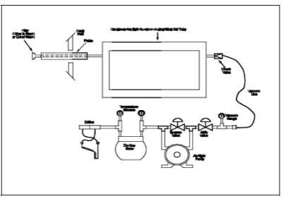
A schematic of the
sampling train used in this reference method is shown in Figure
4-1.
6.1.1 Probe.
Stainless steel or
glass tubing, sufficiently heated to prevent water condensation, and equipped
with a filter, either in-stack (e.g., a plug of glass wool inserted into the end of the probe) or
heated out-of-stack (e.g.,
as described in Method 5), to remove particulate matter. When stack conditions
permit, other metals or plastic tubing may be used for the probe, subject to
the approval of the Administrator.
6.1.2 Condenser.
Same as Method 5, Section 6.1.1.8.
6.1.3 Cooling System.
An ice bath
container, crushed ice, and water (or equivalent), to aid in
condensingmoisture.
6.1.4 Metering System.
Same as in Method 5,
Section 6.1.1.9, except do not use sampling systems designed for flow rates
higher than 0.0283 m3/min (1.0 cfm). Other metering systems, capable
of maintaining a constant sampling rate to within 10 percent and determining
sample gas volume to within 2 percent, may be used, subject to the approval of
the Administrator.
6.1.5 Barometer and Graduated Cylinder and/or Balance.
Same as Method 5, Sections 6.1.2 and 6.2.5,
respectively.
6.2. Approximation Method.
A schematic of the
sampling train used in this approximation method is shown in Figure
4-2.
6.2.1 Probe.
Same as Section
6.1.1.
6.2.2 Condenser.
Two midget impingers,
each with 30-ml capacity, or equivalent.
6.2.3 Cooling System.
Ice bath container,
crushed ice, and water, to aid in condensing moisture in impingers.
6.2.4 Drying Tube.
Tube packed with new
or regenerated 6- to 16-mesh indicating-type silica gel (or equivalent
desiccant), to dry the sample gas and to protect the meter and pump.
6.2.5 Valve.
Needle valve, to
regulate the sample gas flow rate.
6.2.6 Pump.
Leak-free, diaphragm
type, or equivalent, to pull the gas sample through the train.
6.2.7 Volume Meter.
Dry gas meter,
sufficiently accurate to measure the sample volume to within 2 percent, and
calibrated over the range of flow rates and conditions actually encountered
during sampling.
6.2.8 Rate Meter.
Rotameter, or equivalent,
to measure the flow range from 0 to 3 liters/min (0 to 0.11cfm).
6.2.9 Graduated Cylinder. 25-ml.
6.2.10 Barometer.
Same as Method 5,
Section 6.1.2.
6.2.11 Vacuum Gauge.
At least 760-mm
(30-in.) Hg gauge, to be used for the sampling leak check.
7.0 Reagents and Standards. [Reserved]
8.0 Sample Collection, Preservation, Transport, and Storage.
8.1 Reference Method.
The following
procedure is intended for a condenser system (such as the impinger system
described in Section 6.1.1.8 of Method 5) incorporating volumetric analysis to
measure the condensed moisture, and silica gel and gravimetric analysis to
measure the moisture leaving the condenser.
8.1.1 Preliminary Determinations.
8.1.1.1
Unless otherwise specified by the Administrator, a minimum of eight traverse
points shall be used for circular stacks having diameters less than 0.61 m (24
in.), a minimum of nine points shall be used for rectangular stacks having
equivalent diameters less than 0.61 m (24 in.), and a minimum of twelve
traverse points shall be used in all other cases. The traverse points shall be
located according to Method 1. The use of fewer points is subject to the
approval of the Administrator. Select a suitable probe and probe length such
that all traverse points can be sampled. Consider sampling from opposite sides
of the stack (four total sampling ports) for large stacks, to permit use of
shorter probe lengths. Mark the probe with heat resistant tape or by some other
method to
denote the proper
distance into the stack or duct for each sampling point.
8.1.1.2 Select a
total sampling time such that a minimum total gas volume of 0.60 scm (21 scf)
will be collected, at a rate no greater than 0.021 m3/min (0.75 cfm). When both moisture content and pollutant emission
rate are to be determined, the moisture determination shall be simultaneous
with, and for the same total length of time as, the pollutant emission rate
run, unless otherwise specified in an applicable subpart of the standards.
8.1.2 Preparation of Sampling Train.
8.1.2.1 Place known
volumes of water in the first two impingers; alternatively, transfer water into
the first two impingers and record the weight of each impinger (plus water) to
the nearest 0.5 g. Weigh and record the weight of the silica gel to the nearest
0.5 g, and transfer the silica gel to the fourth impinger; alternatively, the
silica gel may first be transferred to the impinger, and the weight of the
silica gel plus impinger recorded.
8.1.2.2 Set up the
sampling train as shown in Figure 4-1. Turn on the probe heater and (if
applicable) the filter heating system to temperatures of approximately 120 °C
(248 °F), to prevent water condensation ahead of the condenser. Allow time for
the temperatures to stabilize. Place crushed ice and water in the ice bath
container.
8.1.3 Leak Check Procedures.
It is recommended,
but not required, that the volume metering system and sampling train be
leak-checked as follows:
8.1.3.1 Metering
System. Same as Method 5, Section 8.4.1.
8.1.3.2 Sampling
Train. Disconnect the probe from the first impinger or (if applicable) from the
filter holder. Plug the inlet to the first impinger (or filter holder), and pull
a 380 mm (15 in.) Hg vacuum. A lower vacuum may be used, provided that it is
not exceeded during the test. A leakage rate in excess of 4 percent of the
average sampling rate or 0.00057 m3/min
(0.020 cfm), whichever is less, is unacceptable. Following the leak check,
reconnect the probe to the sampling train.
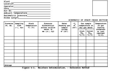
8.1.4 Sampling Train Operation.
During the sampling
run, maintain a sampling rate within 10 percent of constant rate, or as
specified by the Administrator. For each run, record the data required on a
data sheet similar to that shown in Figure 4-3. Be sure
to record the dry gas meter reading at the beginning and end of each sampling
time increment and whenever sampling is halted. Take other appropriate readings
at each sample point at least once during each time increment.
NOTE: When Method 4 is used concurrently with an
isokinetic method (e.g.,
Method 5) the sampling rate should be maintained at isokinetic conditions
rather than 10 percent of constant rate.
8.1.4.1 To begin
sampling, position the probe tip at the first traverse point. Immediately start
the pump, and adjust the flow to the desired rate. Traverse the cross section,
sampling at each traverse point for an equal length of time. Add more ice and,
if necessary, salt to maintain a temperature of less than 20 °C (68 °F) at the
silica gel outlet.
8.1.4.2 After
collecting the sample, disconnect the probe from the first impinger (or from
the filter holder), and conduct a leak check (mandatory) of the sampling train
as described in Section 8.1.3.2. Record the leak rate. If the leakage rate
exceeds the allowable rate, either reject the test results or correct the
sample volume as in Section 12.3 of Method 5.
8.2 Approximation Method.
NOTE: The approximation method described below is
presented only as a suggested method (see Section 2.0).
8.2.1 Place exactly 5
ml water in each impinger. Leak check the sampling train as follows:
Temporarily insert a vacuum gauge at or near the probe inlet. Then, plug the
probe inlet and pull a vacuum of at least 250 mm (10 in.) Hg. Note the time
rate of change of the dry gas meter dial; alternatively, a rotameter (0 to 40
ml/min) may be temporarily attached to the dry gas meter outlet to determine
the leakage rate. A leak rate not in excess of 2 percent of the average
sampling rate is acceptable.
NOTE: Release the probe inlet plug slowly before
turning off the pump.
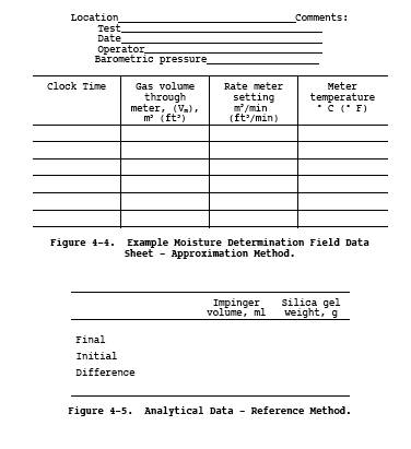
8.2.2 Connect the
probe, insert it into the stack, and sample at a constant rate of 2 liters/min
(0.071 cfm). Continue sampling until the dry gas meter registers about 30
liters (1.1 ft3) or until visible liquid droplets are carried
over from the first impinger to the second. Record temperature, pressure, and
dry gas meter readings as indicated by Figure 4-4.
9.0 Quality Control.
9.1 Miscellaneous
Quality Control Measures.
9.2 Volume Metering
System Checks. Same as Method 5, Section 9.2.
10.0 Calibration and Standardization.
NOTE: Maintain a laboratory log of all calibrations.
10.1 Reference Method.
Calibrate the
metering system, temperature sensors, and barometer according to Method 5, Sections 10.3, 10.5, and 10.6,
respectively.
10.2 Approximation Method.
Calibrate the
metering system and the barometer according to Method
6, Section 10.1 and Method 5, Section 10.6,
respectively.
11.0 Analytical Procedure.
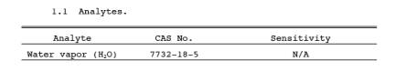
11.1 Reference
Method. Measure the volume of the moisture condensed in each of the impingers
to the nearest ml. Alternatively, if the impingers were weighed prior to
sampling, weigh the impingers after sampling and record the difference in
weight to the nearest 0.5 g. Determine the increase in weight of the silica gel
(or silica gel plus impinger) to the nearest 0.5 g. Record this information
(see example data sheet, Figure 4-5), and calculate the
moisture content, as described in Section 12.0.
11.2 Approximation
Method. Combine the contents of the two impingers, and measure the volume to
the nearest 0.5 ml.
12.0 Data Analysis and Calculations.
Carry out the
following calculations, retaining at least one extra significant figure beyond
that of the acquired data. Round off figures after final calculation.
12.1 Reference Method
12.1.1 Nomenclature.

12.1.2 Volume of Water Vapor Condensed.
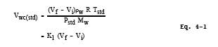
where:
where:
12.1.4 Sample Gas Volume.
K4 = 0.3855 °K/mm Hg for metric units,
= 17.64 °R/in. Hg for
English units.
NOTE: If the post-test leak rate (Section 8.1.4.2)
exceeds the allowable rate, correct the value of Vm in Equation 4-3, as described in Section
12.3 of Method 5.
12.1.5 Moisture Content.
![]()
12.1.6 Verification of Constant Sampling Rate.
For each time
increment, determine the ·Vm. Calculate the
average. If the value for any time increment differs from the average by more
than 10 percent, reject the results, and repeat the run.
12.1.7 In saturated or moisture droplet-laden gas streams
Two calculations of
the moisture content of the stack gas shall be made, one using a value based
upon the saturated conditions (see Section 4.1), and another based upon the
results of the impinger analysis. The lower of these two values of Bws shall be considered correct.
12.2 Approximation Method.
The approximation
method presented is designed to estimate the moisture in the stack gas;
therefore, other data, which are only necessary for accurate moisture
determinations, are not collected. The following equations adequately estimate
the moisture content for the purpose of determining isokinetic sampling rate
settings.
12.2.1 Nomenclature.
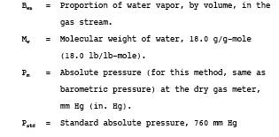
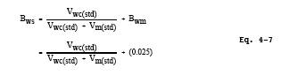
Bwm = Approximate proportion by volume of water
vapor in the gas stream leaving the second impinger, 0.025.
Bws = Water vapor in the gas stream, proportion by
volume.
Mw = Molecular weight of water, 18.0 g/g-mole (18.0 lb/lb-mole).
Pm = Absolute pressure (for this method, same as barometric pressure)
at the dry gas meter, mm Hg (in. Hg).
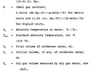
Pstd = Standard absolute pressure, 760 mm Hg (29.92
in. Hg).
R = Ideal gas
constant, 0.06236 [(mm Hg)(m3)]/[(g-mole)(K)] for
metric units and
21.85 [(in. Hg)(ft3)]/[(lb-mole)(°R)] for English units.
Tm = Absolute temperature at meter, °K (°R).
Tstd = Standard absolute temperature, 293 °K (528
°R).
Vf = Final volume of impinger contents, ml.
Vi = Initial volume of impinger contents, ml.
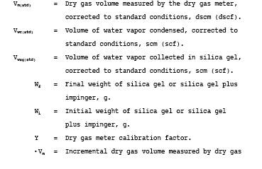
Vm = Dry gas volume measured by dry gas meter, dcm (dcf).
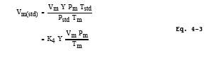
Vm(std) = Dry gas volume measured by dry gas meter,
corrected to standard conditions, dscm (dscf).
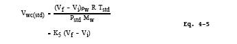
Vwc(std) = Volume of water vapor condensed, corrected to
standard conditions, scm (scf).
Y = Dry gas meter
calibration factor.
![]()
12.2.2 Volume of Water Vapor Collected.
where:
K5 = 0.001333 m3/ml for metric units,
= 0.04706 ft3/ml for English units.
12.2.3 Sample Gas Volume.
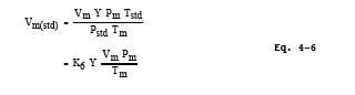
where:
K6 = 0.3855 °K/mm Hg for metric units,
= 17.64 °R/in. Hg for English
units.
12.2.4 Approximate Moisture Content.
13.0 Method Performance. [Reserved]
14.0 Pollution Prevention. [Reserved]
15.0 Waste Management. [Reserved]
16.0 Alternative Procedures.
The procedure
described in Method 5 for determining moisture content is acceptable as a
reference method.
17.0 References.
1. Air Pollution
Engineering Manual (Second Edition). Danielson, J.A. (ed.). U.S. Environmental
Protection Agency, Office of Air Quality Planning and Standards. Research
Triangle Park, NC. Publication No. AP-40. 1973.
2. Devorkin, Howard,
et al. Air Pollution Source Testing Manual. Air Pollution Control District, Los
Angeles, CA. November 1963.
3. Methods for
Determination of Velocity, Volume, Dust and Mist Content of Gases. Western Precipitation
Division of Joy Manufacturing Co. Los Angeles, CA. Bulletin WP-50.1968.
18.0 Tables, Diagrams, Flowcharts, and Validation Data.
Figure
4-1. Moisture Sampling Train -
Reference Method
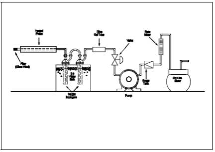
Figure
4-2. Moisture Sampling Train -
Approximation Method.