Method 2F-Determination of Stack Gas Velocity And Volumetric Flow Rate With Three-Dimensional Probes
Note: This method does not include all of the
specifications (e.g., equipment and supplies) and procedures (e.g., sampling) essential
to its performance. Some material has been incorporated from other methods in
this part. Therefore, to obtain reliable results, those using this method
should have a thorough knowledge of at least the following additional test
methods: Methods 1, 2, 3 or 3A, and 4.
3.1. Angle-measuring Device Rotational Offset (RADO).
3.5 Full Scale of Pressure-measuring Device.
3.15 Reference Scribe Line Rotational Offset (RSLO).
3.18 Three-dimensional (3-D) Probe.
3.20 Wind Tunnel Calibration Location.
3.21 Wind Tunnel with Documented Axial Flow.
6.1.1 Five-hole prism-shaped probe.
6.1.2 Five-hole spherical probe.
6.1.4
Other three-dimensional probes. [Reserved]
6.1.7 Probe and system characteristics to ensure horizontal stability.
6.2 Yaw Angle-measuring Device.
6.2.2 Protractor wheel and pointer assembly.
6.2.3 Other yaw angle-measuring devices.
6.3 Probe Supports and Stabilization Devices.
6.4 Differential Pressure Gauges.
6.4.1 Differential pressure-measuring device.
6.4.2 Gauge used for yaw nulling.
6.4.3 Devices for calibrating differential pressure-measuring devices.
6.4.4 Devices used for post-test calibration check.
6.5 Data Display and Capture Devices.
6.7 Stack or Duct Static Pressure Measurement.
6.9 Gas Density Determination Equipment.
6.11 Wind Tunnel for Probe Calibration.
6.11.1 Test section cross-sectional area.
6.11.2 Velocity range and stability.
6.11.3 Flow profile at the calibration location.
6.11.4 Entry ports in the wind tunnel test section.
6.11.5 Pitch angle protractor plate.
7.0
Reagents and Standards. [Reserved]
8.0
Sample Collection and Analysis
8.1 Equipment Inspection and Set-Up
8.2 Horizontal Straightness Check.
8.3 Rotational Position Check.
8.3.1 Angle-measuring device rotational offset.
8.3.2 Sign of angle-measuring device rotational offset.
8.3.3 Independently Adjusted Angle-Measuring Devices
8.5 Zeroing the Differential Pressure-measuring Device.
8.6 Traverse Point Verification.
8.9.1 Yaw angle measurement protocol.
8.9.4 Yaw angle determination.
8.15 Data Recording and Calculations.
9.1 Quality Control Activities.
9.1.1 Range of the differential pressure gauge.
9.1.2 Horizontal stability check.
10.1 Wind Tunnel Qualification Checks.
10.1.1 Velocity pressure cross-check.
10.1.2 Axial flow verification.
10.3 Pre-Calibration Procedures.
10.4 Placement of Reference Scribe Line.
10.5 Yaw Angle Calibration Procedure.
10.6 Pitch Angle and Velocity Pressure Calibrations.
10.8 Calibration of pressure-measuring devices used in field tests.
10.8.1 Post-test calibration check.
10.9 Temperature Gauges. Same as Method 2, section 4.3.
12.0 Data Analysis and Calculations
12.2 Traverse Point Velocity Calculations.
12.2.1 Selection of calibration curves.
12.2.2 Traverse point pitch angle ratio.
12.2.4 Velocity calibration coefficient.
12.2.6 Handling multiple measurements at a traverse point.
12.3 Average Axial Velocity in Stack or Duct.
12.4 Acceptability of Results.
12.5 Average Gas Wet Volumetric Flow Rate in Stack or Duct.
12.6 Average Gas Dry Volumetric Flow Rate in Stack or Duct.
13.0 Method Performance. [Reserved]
14.0 Pollution Prevention. [Reserved]
15.0 Waste Management. [Reserved]
16.1.1 Description of the source.
18.1 Annex A - Rotational Position Check.
18.1.1 Rotational position check with probe outside stack.
18.1.2 Rotational position check with probe in stack.
18.2 Annex B - Angle Measurement Protocol for Protractor Wheel and Pointer Device.
18.3 Annex C - Guideline for Reference Scribe Line Placement.
18.4 Annex D - Determination of Reference Scribe Line Rotational Offset.
1.0 Scope and Application
1.1 This
method is applicable for the determination of yaw angle, pitch angle, axial
velocity and the volumetric flow rate of a gas stream in a stack or duct using
a three-dimensional (3-D) probe. This method may be used only when the average
stack or duct gas velocity is greater than or equal to 20 ft/ sec. When the
above condition cannot be met, alternative procedures, approved by the
Administrator, U.S. Environmental Protection Agency, shall be used to make accurate
flow rate determinations.
2.0 Summary of Method
2.1 A 3-D
probe is used to determine the velocity pressure and the yaw and pitch angles
of the flow velocity vector in a stack or duct. The method determines the yaw
angle directly by rotating the probe to null the pressure across a pair of
symmetrically placed ports on the probe head. The pitch angle is calculated
using probe-specific calibration curves. From these values and a determination
of the stack gas density, the average axial velocity of the stack gas is
calculated. The average gas volumetric flow rate in the stack or duct is then
determined from the average axial velocity.
3.0 Definitions
3.1. Angle-measuring Device Rotational Offset (RADO).
The rotational
position of an angle-measuring device relative to the reference scribe line, as
determined during the pre-test rotational position check described in section 8.3.
3.2 Axial Velocity.
The velocity vector parallel to the axis
of the stack or duct that accounts for the yaw and pitch angle components of
gas flow. The term ‘‘axial’’ is used herein to indicate that the velocity and
volumetric flow rate results account for the measured yaw and pitch components
of flow at each measurement point.
3.3 Calibration Pitot Tube.
The standard (Prandtl type) pitot tube used as a reference
when calibrating a 3-D probe under this method.
3.4 Field Test.
A set of
measurements conducted at a specific unit or exhaust stack/ duct to satisfy the
applicable regulation (e.g., a three-run boiler performance test, a single or
multiple-load nine-run relative accuracy test).
3.5 Full Scale of Pressure-measuring Device.
Full scale refers to the upper limit of the measurement
range displayed by the device. For bi-directional pressure gauges, full scale
includes the entire pressure range from the lowest negative value to the
highest positive value on the pressure scale.
3.6 Main probe.
Refers to the
probe head and that section of probe sheath directly attached to the probe
head. The main probe sheath is distinguished from probe extensions, which are
sections of sheath added onto the main probe to extend its reach.
3.7 ‘‘May,’’ ‘‘Must,’’ ‘‘Shall,’’ ‘‘Should,’’ and
the imperative form of verbs.
3.7.1 ‘‘May’’
is used to indicate that
a provision of this method is optional.
3.7.2 ‘‘Must,’’
‘‘Shall,’’ and the
imperative form of verbs (such as ‘‘record’’ or ‘‘enter’’) are used to indicate
that a provision of this method is mandatory.
3.7.3 ‘‘Should’’
is used to indicate that
a provision of this method is not mandatory, but is highly recommended as good
practice.
3.8 Method 1.
Refers to 40 CFR part 60, appendix A, ‘‘Method 1 - Sample
and velocity traverses for stationary sources.’’
3.9 Method 2.
Refers to 40 CFR part 60, appendix A, ‘‘Method 2 -
Determination of stack gas velocity and volumetric flow rate (Type S pitot
tube).’’
3.10 Method 2G.
Refers to 40
CFR part 60, appendix A, ‘‘Method 2G -
Determination of stack gas velocity and volumetric flow rate with
two-dimensional probes.’’
3.11 Nominal Velocity.
Refers to a wind tunnel velocity setting that approximates
the actual wind tunnel velocity to within ±1.5 m/ sec (±5 ft/sec).
3.12 Pitch Angle.
The angle
between the axis of the stack or duct and the pitch component of flow, i.e.,
the component of the total velocity vector in a plane defined by the traverse
line and the axis of the stack or duct. (Figure 2F-1
illustrates the ‘‘pitch plane.’’) From the standpoint of a tester facing a test
port in a vertical stack, the pitch component of flow is the vector of flow
moving from the center of the stack toward or away from that test port. The
pitch angle is the angle described by this pitch component of flow and the
vertical axis of the stack.
3.13 Readability.
For the
purposes of this method, readability for an analog measurement device is one
half of the smallest scale division. For a digital measurement device, it is
the number of decimals displayed by the device.
3.14 Reference Scribe Line.
A line
permanently inscribed on the main probe sheath (in accordance with section 6.1.6.1) to serve as a reference mark for
determining yaw angles.
3.15 Reference Scribe Line Rotational Offset (RSLO).
The rotational
position of a probe’s reference scribe line relative to the probe’s yaw-null
position, as determined during the yaw angle calibration described in section 10.5.
3.16 Response Time.
The time
required for the measurement system to fully respond to a change from zero
differential pressure and ambient temperature to the stable stack or duct
pressure and temperature readings at a traverse point.
3.17 Tested Probe.
A 3-D probe that is being calibrated.
3.18 Three-dimensional (3-D) Probe.
A directional
probe used to determine the velocity pressure and yaw and pitch angles in a
flowing gas stream.
3.19 Traverse Line.
A diameter or
axis extending across a stack or duct on which measurements of differential
pressure and flow angles are made.
3.20 Wind Tunnel Calibration Location.
A point, line, area, or volume within the wind tunnel test
section at, along, or within which probes are calibrated. At a particular wind
tunnel velocity setting, the average velocity pressures at specified points at,
along, or within the calibration location shall vary by no more than 2 percent
or 0.3 mm H2O (0.01 in. H2O), whichever is less restrictive, from the average
velocity pressure at the calibration pitot tube location. Air flow at this
location shall be axial, i.e., yaw and pitch angles within ±° of 0°. Compliance
with these flow criteria shall be demonstrated by performing the procedures
prescribed in sections 10.1.1 and 10.1.2. For
circular tunnels, no part of the calibration location may be closer to the
tunnel wall than 10.2 cm (4 in.) or 25 percent of the tunnel diameter,
whichever is farther from the wall. For elliptical or rectangular tunnels, no
part of the calibration location may be closer to the tunnel wall than 10.2 cm
(4 in.) or 25 percent of the applicable cross-sectional axis, whichever is
farther from the wall.
3.21 Wind Tunnel with Documented Axial Flow.
A wind tunnel
facility documented as meeting the provisions of sections 10.1.1 (velocity
pressure crosscheck) and 10.1.2 (axial flow verification) using the procedures
described in these sections or alternative procedures determined to be
technically equivalent.
3.22 Yaw Angle.
The angle between
the axis of the stack or duct and the yaw component of flow, i.e., the
component of the total velocity vector in a plane perpendicular to the traverse
line at a particular traverse point. (Figure 2F-1 illustrates the ‘‘yaw
plane.’’) From the standpoint of a tester facing a test port in a vertical
stack, the yaw component of flow is the vector of flow moving to the left or
right from the center of the stack as viewed by the tester. (This is sometimes
referred to as ‘‘vortex flow,’’ i.e., flow around the centerline of a stack or
duct.) The yaw angle is the angle described by this yaw component of flow and
the vertical axis of the stack. The algebraic sign convention is illustrated in
Figure 2F-2.
3.23 Yaw Nulling.
A procedure in which a probe is rotated about its axis in a
stack or duct until a zero differential pressure reading (‘‘yaw null’’) is
obtained. When a 3-D probe is yaw-nulled, its impact pressure port (P1) faces
directly into the direction of flow in the stack or duct and the differential
pressure between pressure ports P2 and P3 is zero.
4.0 Interferences. [Reserved]
5.0 Safety.
5.1 This test
method may involve hazardous operations and the use of hazardous materials or
equipment. This method does not purport to address all of the safety problems
associated with its use. It is the responsibility of the user to establish and
implement appropriate safety and health practices and to determine the
applicability of regulatory limitations before using this test method.
6.0 Equipment and Supplies
6.1 Three-dimensional Probes.
The 3-D probes
as specified in subsections 6.1.1 through 6.1.3 below qualify for use based on
comprehensive wind tunnel and field studies involving both inter-and intra-probe
comparisons by multiple test teams. Other types of probes shall not be used
unless approved by the Administrator. Each 3-D probe shall have a unique
identification number or code permanently marked on the main probe sheath. The
minimum recommended diameter of the sensing head of any probe used under this
method is 2.5 cm (1 in.). Each probe shall be calibrated prior to use according
to the procedures in section 10. Manufacturer-supplied calibration data shall
be used as example information only, except when the manufacturer calibrates
the 3-D probe as specified in section 10 and provides complete documentation.
6.1.1 Five-hole prism-shaped probe.
This type of
probe consists of five pressure taps in the flat facets of a prism-shaped
sensing head. The pressure taps are numbered 1 through 5, with the pressures
measured at each hole referred to as P1, P2, P3, P4, and P5, respectively. Figure 2F-3 is an illustration of the placement of pressure
taps on a commonly available five-hole prism-shaped probe, the 2.5-cm (1-in.)
DAT probe. (Note: Mention of trade names or specific products does not
constitute endorsement by the U.S. Environmental Protection Agency.) The
numbering arrangement for the prism-shaped sensing head presented in Figure
2F-3 shall be followed for correct operation of the probe. A brief description
of the probe measurements involved is as follows: the differential pressure
P2-P3 is used to yaw null the probe and determine the yaw angle; the
differential pressure P4-P5 is a function of pitch angle; and the differential
pressure P1-P2 is a function of total velocity.
6.1.2 Five-hole spherical probe.
This type of
probe consists of five pressure taps in a spherical sensing head. As with the
prism-shaped probe, the pressure taps are numbered 1 through 5, with the
pressures measured at each hole referred to as P1, P2, P3, P4, and P5,
respectively. However, the P4 and P5 pressure taps are in the reverse location
from their respective positions on the prism-shaped probe head. The
differential pressure P2-P3 is used to yaw null the probe and determine the yaw
angle; the differential pressure P4-P5 is a function of pitch angle; and the
differential pressure P1-P2 is a function of total velocity. A diagram of a typical
spherical probe sensing head is presented in Figure 2F-4.
Typical probe dimensions are indicated in the illustration.
6.1.3 A manual 3-D probe
Refers to a five-hole
prism-shaped or spherical probe that is positioned at individual traverse
points and yaw nulled manually by an operator. An automated 3-D probe refers to
a system that uses a computer-controlled motorized mechanism to position the
five-hole prism-shaped or spherical head at individual traverse points and
perform yaw angle determinations.
6.1.4 Other three-dimensional probes. [Reserved]
6.1.5 Probe sheath.
The probe
shaft shall include an outer sheath to: (1) provide a surface for inscribing a permanent
reference scribe line, (2) accommodate attachment of an angle-measuring device
to the probe shaft, and (3) facilitate precise rotational movement of the probe
for determining yaw angles. The sheath shall be rigidly attached to the probe
assembly and shall enclose all pressure lines from the probe head to the
farthest position away from the probe head where an angle-measuring device may
be attached during use in the field. The sheath of the fully assembled probe
shall be sufficiently rigid and straight at all rotational positions such that,
when one end of the probe shaft is held in a horizontal position, the fully
extended probe meets the horizontal straightness specifications indicated in
section 8.2 below.
6.1.6 Scribe lines.
6.1.6.1 Reference scribe line. A permanent line, no greater
than 1.6 mm (1/16 in.) in width, shall be inscribed on each manual probe that
will be used to determine yaw angles of flow. This line shall be placed on the
main probe sheath in accordance with the procedures described in section 10.4 and is used as a reference position for
installation of the yaw angle-measuring device on the probe. At the discretion
of the tester, the scribe line may be a single line segment placed at a
particular position on the probe sheath (e.g., near the probe head), multiple
line segments placed at various locations along the length of the probe sheath
(e.g., at every position where a yaw angle-measuring device may be mounted), or
a single continuous line extending along the full length of the probe sheath.
6.1.6.2 Scribe
line on probe extensions. A permanent line may also be inscribed on any probe
extension that will be attached to the main probe in performing field testing.
This allows a yaw angle-measuring device mounted on the extension to be readily
aligned with the reference scribe line on the main probe sheath.
6.1.6.3
Alignment specifications. This specification shall be met separately, using the
procedures in section 10.4.1, on the main probe and
on each probe extension. The rotational position of the scribe line or scribe
line segments on the main probe or any probe extension must not vary by more
than 2°. That is, the difference between the minimum and maximum of all of the
rotational angles that are measured along the full length of the main probe or
the probe extension must not exceed 2°.
6.1.7 Probe and system characteristics to ensure
horizontal stability.
6.1.7.1 For
manual probes, it is recommended that the effective length of the probe
(coupled with a probe extension, if necessary) be at least 0.9 m (3 ft.) longer
than the farthest traverse point mark on the probe shaft away from the probe
head. The operator should maintain the probe’s horizontal stability when it is
fully inserted into the stack or duct. If a shorter probe is used, the probe
should be inserted through a bushing sleeve, similar to the one shown in Figure 2F-5, that is installed on the test port; such a
bushing shall fit snugly around the probe and be secured to the stack or duct
entry port in such a manner as to maintain the probe’s horizontal stability
when fully inserted into the stack or duct.
6.1.7.2 An
automated system that includes an external probe casing with a transport system
shall have a mechanism for maintaining horizontal stability comparable to that
obtained by manual probes following the provisions of this method. The
automated probe assembly shall also be constructed to maintain the alignment
and position of the pressure ports during sampling at each traverse point. The
design of the probe casing and transport system shall allow the probe to be
removed from the stack or duct and checked through direct physical measurement
for angular position and insertion depth.
6.1.8 Tube Connect Diameter
The tubing
that is used to connect the probe and the pressure-measuring device should have
an inside diameter of at least 3.2 mm (1/8 in.), to reduce the time required
for pressure equilibration, and should be as short as practicable.
6.2 Yaw Angle-measuring Device.
One of the
following devices shall be used for measurement of the yaw angle of flow.
6.2.1 Digital inclinometer.
This refers to
a digital device capable of measuring and displaying the rotational position of
the probe to within ±1°. The device shall be able to be locked into position on
the probe sheath or probe extension, so that it indicates the probe’s
rotational position throughout the test. A rotational position collar block
that can be attached to the probe sheath (similar to the collar shown in Figure 2F-6) may be required to lock the digital
inclinometer into position on the probe sheath.
6.2.2 Protractor wheel and pointer assembly.
This
apparatus, similar to that shown in Figure 2F-7,
consists of the following components.
6.2.2.1 A
protractor wheel that can be attached to a port opening and set in a fixed
rotational position to indicate the yaw angle position of the probe’s scribe
line relative to the longitudinal axis of the stack or duct. The protractor
wheel must have a measurement ring on its face that is no less than 17.8 cm (7
in.) in diameter, shall be able to be rotated to any angle and then locked into
position on the stack or duct port, and shall indicate angles to a resolution
of 1°.
6.2.2.2 A
pointer assembly that includes an indicator needle mounted on a collar that can
slide over the probe sheath and be locked into a fixed rotational position on
the probe sheath. The pointer needle shall be of sufficient length, rigidity,
and sharpness to allow the tester to determine the probe’s angular position to
within 1° from the markings on the protractor wheel. Corresponding to the
position of the pointer, the collar must have a scribe line to be used in
aligning the pointer with the scribe line on the probe sheath.
6.2.3 Other yaw angle-measuring devices.
Other
angle-measuring devices with a manufacturer’s specified precision of 1° or
better may be used, if approved by the Administrator.
6.3 Probe Supports and Stabilization Devices.
When probes
are used for determining flow angles, the probe head should be kept in a stable
horizontal position. For probes longer than 3.0 m (10 ft.), the section of the
probe that extends outside the test port shall be secured. Three alternative
devices are suggested for maintaining the horizontal position and stability of
the probe shaft during flow angle determinations and velocity pressure
measurements: (1) Monorails installed above each port, (2) probe stands on
which the probe shaft may be rested, or (3) bushing sleeves of sufficient
length secured to the test ports to maintain probes in a horizontal position.
Comparable provisions shall be made to ensure that automated systems maintain
the horizontal position of the probe in the stack or duct. The physical
characteristics of each test platform may dictate the most suitable type of
stabilization device. Thus, the choice of a specific stabilization device is
left to the judgment of the testers.
6.4 Differential Pressure Gauges.
The pressure
(DeltaP) measuring devices used during wind tunnel calibrations and field
testing shall be either electronic manometers (e.g., pressure transducers),
fluid manometers, or mechanical pressure gauges (e.g., Magnehelic® gauges). Use
of electronic manometers is recommended. Under low velocity conditions, use of
electronic manometers may be necessary to obtain acceptable measurements.
6.4.1 Differential pressure-measuring device.
This refers to
a device capable of measuring pressure differentials and having a readability
of ±1 percent of full scale. The device shall be capable of accurately
measuring the maximum expected pressure differential. Such devices are used to
determine the following pressure measurements: velocity pressure, static
pressure, yaw-null pressure, and pitch-angle pressure. For an inclined-vertical
manometer, the readability specification of ±1 percent shall be met separately
using the respective full-scale upper limits of the inclined and vertical
portions of the scales. To the extent practicable, the device shall be selected
such that most of the pressure readings are between 10 and 90 percent of the
device’s full-scale measurement range (as defined in section 3.5). Typical
velocity pressure (P1-P2 ranges for both the prism-shaped probe and the
spherical probe are 0 to 1.3 cm H2O (0 to 0.5 in. H2O), 0 to 5.1 cm H2O (0 to 2
in. H2O), and 0 to 12.7 cm H2O (0 to 5 in. H2O). The pitch angle (P4-P5)
pressure range is typically -6.4 to +6.4 mm H2O (-0.25 to +0.25 in. H2O) or
-12.7 to +12.7 mm H2O (-0.5 to +0.5 in. H2O) for the prism-shaped probe, and
-12.7 to +12.7 mm H2O (-0.5 to +0.5 in. H2O) or -5.1 to +5.1 cm H2O (-2 to +2
in. H2O) for the spherical probe. The pressure range for the yaw null (P2-P3)
readings is typically -12.7 to +12.7 mm H2O (-0.5 to +0.5 in. H2O) for both
probe types. In addition, pressure-measuring devices should be selected such
that the zero does not drift by more than 5 percent of the average expected
pressure readings to be encountered during the field test. This is particularly
important under low pressure conditions.
6.4.2 Gauge used for yaw nulling.
The
differential pressure-measuring device chosen for yaw nulling the probe during
the wind tunnel calibrations and field testing shall be bi-directional, i.e.,
capable of reading both positive and negative differential pressures. If a
mechanical, bi-directional pressure gauge is chosen, it shall have a full scale
range no greater than 2.6 cm H2O (1 in. H2O) [i.e., -1.3 to +1.3 cm H2O (-0.5
in. to +0.5 in.)].
6.4.3 Devices for calibrating differential pressure-measuring devices.
A precision
manometer (e.g., a U-tube, inclined, or inclined-vertical manometer, or
micromanometer) or NIST (National Institute of Standards and Technology)
traceable pressure source shall be used for calibrating differential
pressure-measuring devices. The device shall be maintained under laboratory
conditions or in a similar protected environment (e.g., a climate-controlled
trailer). It shall not be used in field tests. The precision manometer shall
have a scale gradation of 0.3 mm H2O (0.01 in. H2O), or less, in the range of 0
to 5.1 cm H2O (0 to 2 in. H2O) and 2.5 mm H2O (0.1 in. H2O), or less, in the
range of 5.1 to 25.4 cm H2O (2 to 10 in. H2O). The manometer shall have
manufacturer’s documentation that it meets an accuracy specification of at
least 0.5 percent of full scale. The NIST-traceable pressure source shall be
recertified annually.
6.4.4 Devices used for post-test calibration check.
A precision
manometer meeting the specifications in section 6.4.3, a pressure-measuring
device or pressure source with a documented calibration traceable to NIST, or
an equivalent device approved by the Administrator shall be used for the
post-test calibration check. The pressure-measuring device shall have a
readability equivalent to or greater than the tested device. The pressure
source shall be capable of generating pressures between 50 and 90 percent of
the range of the tested device and known to within ±1 percent of the full scale
of the tested device. The pressure source shall be recertified annually.
6.5 Data Display and Capture Devices.
Electronic
manometers (if used) shall be coupled with a data display device (such as a
digital panel meter, personal computer display, or strip chart) that allows the
tester to observe and validate the pressure measurements taken during testing.
They shall also be connected to a data recorder (such as a data logger or a
personal computer with data capture software) that has the ability to compute
and retain the appropriate average value at each traverse point, identified by
collection time and traverse point.
6.6 Temperature Gauges.
For field
tests, a thermocouple or resistance temperature detector (RTD) capable of
measuring temperature to within ±3°C (±5°F) of the stack or duct temperature
shall be used. The thermocouple shall be attached to the probe such that the
sensor tip does not touch any metal and is located on the opposite side of the
probe head from the pressure ports so as not to interfere with the gas flow
around the probe head. The position of the thermocouple relative to the
pressure port face openings shall be in the same configuration as used for the
probe calibrations in the wind tunnel. Temperature gauges used for wind tunnel
calibrations shall be capable of measuring temperature to within ±0.6°C (±1°F)
of the temperature of the flowing gas stream in the wind tunnel.
6.7 Stack or Duct Static Pressure Measurement.
The
pressure-measuring device used with the probe shall be as specified in section
6.4 of this method. The static tap of a standard (Prandtl type) pitot tube or
one leg of a Type S pitot tube with the face opening planes positioned parallel
to the gas flow may be used for this measurement. Also acceptable is the
pressure differential reading of P1-Pbar from a five-hole prism-shaped probe
(e.g., Type DA or DAT probe) with the P1 pressure port face opening positioned
parallel to the gas flow in the same manner as the Type S probe. However, the
spherical probe, as specified in section 6.1.2, is unable to provide this
measurement and shall not be used to take static pressure measurements. Static
pressure measurement is further described in section 8.11.
6.8 Barometer.
Same as Method
2, section 2.5.
6.9 Gas Density Determination Equipment.
Method 3 or 3A
shall be used to determine the dry molecular weight of the stack gas. Method 4
shall be used for moisture content determination and computation of stack gas
wet molecular weight. Other methods may be used, if approved by the
Administrator.
6.10 Calibration Pitot Tube.
Same as Method
2, section 2.7.
6.11 Wind Tunnel for Probe Calibration.
Wind tunnels
used to calibrate velocity probes must meet the following design
specifications.
6.11.1 Test section cross-sectional area.
The flowing
gas stream shall be confined within a circular, rectangular, or elliptical
duct. The cross-sectional area of the tunnel must be large enough to ensure
fully developed flow in the presence of both the calibration pitot tube and the
tested probe. The calibration site, or ‘‘test section,’’ of the wind tunnel
shall have a minimum diameter of 30.5 cm (12 in.) for circular or elliptical
duct cross-sections or a minimum width of 30.5 cm (12 in.) on the shorter side
for rectangular cross-sections. Wind tunnels shall meet the probe blockage
provisions of this section and the qualification requirements prescribed in
section 10.1. The projected area of the portion of the probe head, shaft, and
attached devices inside the wind tunnel during calibration shall represent no
more than 4 percent of the cross-sectional area of the tunnel. The projected
area shall include the combined area of the calibration pitot tube and the
tested probe if both probes are placed simultaneously in the same
cross-sectional plane in the wind tunnel, or the larger projected area of the
two probes if they are placed alternately in the wind tunnel.
6.11.2 Velocity range and stability.
The wind
tunnel should be capable of maintaining velocities between 6.1 m/sec and 30.5
m/sec (20 ft/sec and 100 ft/sec). The wind tunnel shall produce fully developed
flow patterns that are stable and parallel to the axis of the duct in the test
section.
6.11.3 Flow profile at the calibration location.
The wind
tunnel shall provide axial flow within the test section calibration location
(as defined in section 3.20). Yaw and pitch angles in the calibration location
shall be within ±3° of 0°. The procedure for determining that this requirement
has been met is described in section 10.1.2.
6.11.4 Entry ports in the wind tunnel test
section.
6.11.4.1 Port for
tested probe. A port shall be constructed for the tested probe. The port should
have an elongated slot parallel to the axis of the duct at the test section.
The elongated slot should be of sufficient length to allow attaining all the
pitch angles at which the probe will be calibrated for use in the field. To
facilitate alignment of the probe during calibration, the test section should
include a window constructed of a transparent material to allow the tested
probe to be viewed. This port shall be located to allow the head of the tested
probe to be positioned within the calibration location (as defined in section
3.20) at all pitch angle settings.
6.11.4.2 Port
for verification of axial flow. Depending on the equipment selected to conduct
the axial flow verification prescribed in section 10.1.2, a second port,
located 90° from the entry port for the tested probe, may be needed to allow
verification that the gas flow is parallel to the central axis of the test
section. This port should be located and constructed so as to allow one of the
probes described in section 10.1.2.2 to access the same test point(s) that are
accessible from the port described in section 6.11.4.1.
6.11.4.3 Port
for calibration pitot tube. The calibration pitot tube shall be used in the
port for the tested probe or a separate entry port. In either case, all
measurements with the calibration pitot tube shall be made at the same point
within the wind tunnel over the course of a probe calibration. The measurement
point for the calibration pitot tube shall meet the same specifications for
distance from the wall and for axial flow as described in section 3.20 for the
wind tunnel calibration location.
6.11.5 Pitch angle protractor plate.
A protractor
plate shall be attached directly under the port used with the tested probe and
set in a fixed position to indicate the pitch angle position of the probe
relative to the longitudinal axis of the wind tunnel duct (similar to Figure 2F-8). The protractor plate shall indicate angles in
5° increments with a minimum resolution of ±2°. The tested probe shall be able
to be locked into position at the desired pitch angle delineated on the
protractor. The probe head position shall be maintained within the calibration
location (as defined in section 3.20) in the test section of the wind tunnel
during all tests across the range of pitch angles.
7.0 Reagents and Standards. [Reserved]
8.0 Sample Collection and Analysis
8.1 Equipment Inspection and Set-Up
8.1.1 All
probes, differential pressure-measuring devices, yaw angle-measuring devices,
thermocouples, and barometers shall have a current, valid calibration before
being used in a field test. (See sections 10.3.3, 10.3.4, and 10.5 through10.10
for the applicable calibration requirements.)
8.1.2 Before
each field use of a 3-D probe, perform a visual inspection to verify the
physical condition of the probe head according to the procedures in section
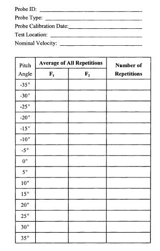
10.2. Record the inspection results on a form similar to Table
2F-1. If there is visible damage to the 3-D probe, the probe shall not be
used until it is recalibrated.
8.1.3 After
verifying that the physical condition of the probe head is acceptable, set up
the apparatus using lengths of flexible tubing that are as short as
practicable. Surge tanks installed between the probe and pressure-measuring
device may be used to dampen pressure fluctuations provided that an adequate
measurement response time (see section 8.8) is maintained.
8.2 Horizontal Straightness Check.
A horizontal
straightness check shall be performed before the start of each field test,
except as otherwise specified in this section. Secure the fully assembled probe
(including the probe head and all probe shaft extensions) in a horizontal
position using a stationary support at a point along the probe shaft
approximating the location of the stack or duct entry port when the probe is
sampling at the farthest traverse point from the stack or duct wall. The probe
shall be rotated to detect bends. Use an angle-measuring device or trigonometry
to determine the bend or sag between the probe head and the secured end. (See Figure 2F-9.) Probes that are bent or sag by more than 5°
shall not be used. Although this check does not apply when the probe is used
for a vertical traverse, care should be taken to avoid the use of bent probes
when conducting vertical traverses. If the probe is constructed of a rigid
steel material and consists of a main probe without probe extensions, this
check need only be performed before the initial field use of the probe, when
the probe is recalibrated, when a change is made to the design or material of
the probe assembly, and when the probe becomes bent. With such probes, a visual
inspection shall be made of the fully assembled probe before each field test to
determine if a bend is visible. The probe shall be rotated to detect bends. The
inspection results shall be documented in the field test report. If a bend in
the probe is visible, the horizontal straightness check shall be performed
before the probe is used.
8.3 Rotational Position Check.
Before each
field test, and each time an extension is added to the probe during a field test,
a rotational position check shall be performed on all manually operated probes
(except as noted in section 8.3.5, below) to ensure that, throughout testing,
the angle-measuring device is either: aligned to within ±1° of the rotational
position of the reference scribe line; or is affixed to the probe such that the
rotational offset of the device from the reference scribe line is known to
within ±1°. This check shall consist of direct measurements of the rotational
positions of the reference scribe line and angle-measuring device sufficient to
verify that these specifications are met. Annex A in
section 18 of this method gives recommended procedures for performing the
rotational position check, and Table 2F-2 gives an
example data form. Procedures other than those recommended in Annex A in
section 18 may be used, provided they demonstrate whether the alignment
specification is met and are explained in detail in the field test report.
8.3.1 Angle-measuring device rotational offset.
The tester
shall maintain a record of the angle-measuring device rotational offset, RADO,
as defined in section 3.1. Note that RADO is assigned a value of 0° when the
angle-measuring device is aligned to within ±1° of the rotational position of
the reference scribe line. The RADO shall be used to determine the yaw angle of
flow in accordance with section 8.9.4.
8.3.2 Sign of angle-measuring device rotational offset.
The sign of
RADO is positive when the angle-measuring device (as viewed from the ‘‘tail’’
end of the probe) is positioned in a clockwise direction from the reference
scribe line and negative when the device is positioned in a counterclockwise
direction from the reference scribe line.
8.3.3 Independently Adjusted Angle-Measuring Devices
Angle-measuring
devices that can be independently adjusted (e.g., by means of a set screw),
after being locked into position on the probe sheath, may be used. However, the
RADO must also take into account this adjustment.
8.3.4 Post-test check.
If probe
extensions remain attached to the main probe throughout the field test, the
rotational position check shall be repeated, at a minimum, at the completion of
the field test to ensure that the angle-measuring device has remained within
±2° of its rotational position established prior to testing. At the discretion
of the tester, additional checks may be conducted after completion of testing
at any sample port or after any test run. If the ±2° specification is not met,
all measurements made since the last successful rotational position check must
be repeated. Section 18.1.1.3 of Annex A provides
an example procedure for performing the post-test check.
8.3.5 Exceptions.
8.3.5.1 A
rotational position check need not be performed if, for measurements taken at
all velocity traverse points, the yaw angle-measuring device is mounted and
aligned directly on the reference scribe line specified in sections 6.1.6.1 and
6.1.6.3 and no independent adjustments, as described in section 8.3.3, are made
to the device’s rotational position.
8.3.5.2 If
extensions are detached and reattached to the probe during a field test, a
rotational position check need only be performed the first time an extension is
added to the probe, rather than each time the extension is re-attached, if the
probe extension is designed to be locked into a mechanically fixed rotational
position (e.g., through use of interlocking grooves) that can re-establish the
initial rotational position to within ±1°.
8.4 Leak Checks.
A pre-test
leak check shall be conducted before each field test. A post-test check shall
be performed at the end of the field test, but additional leak checks may be conducted
after any test run or group of test runs. The post-test check may also serve as
the pre-test check for the next group of test runs. If any leak check is
failed, all runs since the last passed leak check are invalid. While performing
the leak check procedures, also check each pressure device’s responsiveness to
the changes in pressure.
8.4.1 To
perform the leak check, pressurize the probe’s P1 pressure port until at least
7.6 cm H2O (3 in. H2O) pressure, or a pressure corresponding to approximately
75 percent of the pressure-measuring device’s measurement scale, whichever is
less, registers on the device; then, close off the pressure port. The pressure
shall remain stable [±2.5 mm H2O (±0.10 in. H2O)] for at least 15 seconds.
Check the P2, P3, P4, and P5 pressure ports in the same fashion. Other
leak-check procedures may be used, if approved by the Administrator.
8.5 Zeroing the Differential Pressure-measuring Device.
Zero each
differential pressure-measuring device, including the device used for yaw
nulling, before each field test. At a minimum, check the zero after each field
test. A zero check may also be performed after any test run or group of test
runs. For fluid manometers and mechanical pressure gauges (e.g., Magnehelic®
gauges), the zero reading shall not deviate from zero by more than ±0.8 mm H2O
(±0.03 in. H2O) or one minor scale division, whichever is greater, between
checks. For electronic manometers, the zero reading shall not deviate from zero
between checks by more than: ±0.3 mm H2O (±0.01 in. H2O), for full scales less
than or equal to 5.1 cm H2O (2.0 in. H2O); or ±0.8 mm H2O (±0.03 in. H2O), for
full scales greater than 5.1 cm H2O (2.0 in. H2O). (Note: If negative zero
drift is not directly readable, estimate the reading based on the position of
the gauge oil in the manometer or of the needle on the pressure gauge.) In
addition, for all pressure-measuring devices except those used exclusively for
yaw nulling, the zero reading shall not deviate from zero by more than 5
percent of the average measured differential pressure at any distinct process
condition or load level. If any zero check is failed at a specific process
condition or load level, all runs conducted at that process condition or load
level since the last passed zero check are invalid.
8.6 Traverse Point Verification.
The number and
location of the traverse points shall be selected based on Method 1 guidelines.
The stack or duct diameter and port nipple lengths, including any extension of
the port nipples into stack or duct, shall be verified the first time the test
is performed; retain and use this information for subsequent field tests,
updating it as required. Physically measure the stack or duct dimensions or use
a calibrated laser device; do not use engineering drawings of the stack or
duct. The probe length necessary to reach each traverse point shall be recorded
to within ±6.4 mm (±1/4 in.) and, for manual probes, marked on the probe
sheath. In determining these lengths, the tester shall take into account both
the distance that the port flange projects outside of the stack and the depth
that any port nipple extends into the gas stream. The resulting point positions
shall reflect the true distances from the inside wall of the stack or duct, so
that when the tester aligns any of the markings with the outside face of the
stack port, the probe’s impact port shall be located at the appropriate
distance from the inside wall for the respective Method 1 traverse point.
Before beginning testing at a particular location, an out-of-stack or duct
verification shall be performed on each probe that will be used to ensure that
these position markings are correct. The distances measured during the
verification must agree with the previously calculated distances to within ±1/
4 in. For manual probes, the traverse point positions shall be verified by
measuring the distance of each mark from the probe’s P1 pressure port. A
comparable out-of-stack test shall be performed on automated probe systems. The
probe shall be extended to each of the prescribed traverse point positions.
Then, the accuracy of the positioning for each traverse point shall be verified
by measuring the distance between the port flange and the probe’s P1 pressure
port.
8.7 Probe Installation.
Insert the
probe into the test port. A solid material shall be used to seal the port.
8.8 System Response Time.
Determine the
response time of the probe measurement system. Insert and position the ‘‘cold’’
probe (at ambient temperature and pressure) at any Method 1 traverse point.
Read and record the probe’s P1-P2 differential pressure, temperature, and
elapsed time at 15-second intervals until stable readings for both pressure and
temperature are achieved. The response time is the longer of these two elapsed
times. Record the response time.
8.9 Sampling.
8.9.1 Yaw angle measurement protocol.
With manual
probes, yaw angle measurements may be obtained in two alternative ways during
the field test, either by using a yaw angle-measuring device (e.g., digital
inclinometer) affixed to the probe, or using a protractor wheel and pointer
assembly. For horizontal traversing, either approach may be used. For vertical
traversing, i.e., when measuring from on top or into the bottom of a horizontal
duct, only the protractor wheel and pointer assembly may be used. With
automated probes, curve-fitting protocols may be used to obtain yaw angle
measurements.
8.9.1.1 If a
yaw angle-measuring device affixed to the probe is to be used, lock the device
on the probe sheath, aligning it either on the reference scribe line or in the
rotational offset position established under section 8.3.1.
8.9.1.2 If a protractor
wheel and pointer assembly is to be used, follow the procedures in Annex B of this method.
8.9.1.3 Other
yaw angle-determination procedures. If approved by the Administrator, other
procedures for determining yaw angle may be used, provided that they are
verified in a wind tunnel to be able to perform the yaw angle calibration
procedure as described in section 10.5.
8.9.2 Sampling strategy.
At each
traverse point, first yaw-null the probe, as described in section 8.9.3, below.
Then, with the probe oriented into the direction of flow, measure and record
the yaw angle, the differential pressures and the temperature at the traverse
point, after stable readings are achieved, in accordance with sections 8.9.4
and 8.9.5. At the start of testing in each port (i.e., after a probe has been
inserted into the flue gas stream), allow at least the response time to elapse
before beginning to take measurements at the first traverse point accessed from
that port. Provided that the probe is not removed from the flue gas stream,
measurements may be taken at subsequent traverse points accessed from the same
test port without waiting again for the response time to elapse.
8.9.3 Yaw-nulling procedure.
In preparation
for yaw angle determination, the probe must first be yaw nulled. After
positioning the probe at the appropriate traverse point, perform the following
procedures.
8.9.3.1 Rotate
the probe until a null differential pressure reading (the difference in
pressures across the P2 and P3 pressure ports is zero, i.e., P2 = P3) is
indicated by the yaw angle pressure gauge. Read and record the angle displayed
by the angle-measuring device.
8.9.3.2 Sign
of the measured angle. The angle displayed on the angle-measuring device is
considered positive when the probe’s impact pressure port (as viewed from the
‘‘tail’’ end of the probe) is oriented in a clockwise rotational position
relative to the stack or duct axis and is considered negative when the probe’s
impact pressure port is oriented in a counterclockwise rotational position (see
Figure 2F-10).
8.9.4 Yaw angle determination.
After
performing the yaw-nulling procedure in section 8.9.3, determine the yaw angle
of flow according to one of the following procedures. Special care must be
observed to take into account the signs of the recorded angle and all offsets.
8.9.4.1
Direct-reading. If all rotational offsets are zero or if the angle-measuring
device rotational offset (RADO) determined in section 8.3 exactly compensates
for the scribe line rotational offset (RSLO) determined in section 10.5, then
the magnitude of the yaw angle is equal to the displayed angle-measuring device
reading from section 8.9.3.1. The algebraic sign of the yaw angle is determined
in accordance with section 8.9.3.2.
Note: Under certain circumstances (e.g.,
testing of horizontal ducts), a 90° adjustment to the angle-measuring device
readings may be necessary to obtain the correct yaw angles.
8.9.4.2
Compensation for rotational offsets during data reduction. When the
angle-measuring device rotational offset does not compensate for reference
scribe line rotational offset, the following procedure shall be used to
determine the yaw angle: (a) Enter the reading indicated by the angle-measuring
device from section 8.9.3.1. (b) Associate the proper algebraic sign from
section 8.9.3.2 with the reading in step (a). (c) Subtract the reference scribe
line rotational offset, RSLO, from the reading in step (b). (d) Subtract the
angle-measuring device rotational offset, RADO, if any, from the result
obtained in step (c). (e) The final result obtained in step (d) is the yaw
angle of flow.
Note: It may be necessary to first apply a 90°
adjustment to the reading in step (a), in order to obtain the correct yaw
angle.
8.9.4.3 Record
the yaw angle measurements on a form similar to Table 2F-3.
8.9.5 Velocity determination.
Maintain the
probe rotational position established during the yaw angle determination. Then,
begin recording the pressure-measuring device readings for the impact pressure
(P1-P2) and pitch angle pressure (P4-P5). These pressure measurements shall be
taken over a sampling period of sufficiently long duration to ensure
representative readings at each traverse point. If the pressure measurements
are determined from visual readings of the pressure device or display, allow sufficient
time to observe the pulsation in the readings to obtain a sight-weighted
average, which is then recorded manually. If an automated data acquisition
system (e.g., data logger, computer-based data recorder, strip chart recorder)
is used to record the pressure measurements, obtain an integrated average of
all pressure readings at the traverse point. Stack or duct gas temperature
measurements shall be recorded, at a minimum, once at each traverse point.
Record all necessary data as shown in the example field data form (Table 2F-3).
8.9.6 Alignment check.
For manually
operated probes, after the required yaw angle and differential pressure and
temperature measurements have been made at each traverse point, verify (e.g.,
by visual inspection) that the yaw angle-measuring device has remained in
proper alignment with the reference scribe line or with the rotational offset
position established in section 8.3. If, for a particular traverse point, the
angle-measuring device is found to be in proper alignment, proceed to the next
traverse point; otherwise, re-align the device and repeat the angle and
differential pressure measurements at the traverse point. In the course of a
traverse, if a mark used to properly align the angle-measuring device (e.g., as
described in section 18.1.1.1) cannot be located, re-establish the alignment
mark before proceeding with the traverse.
8.10 Probe Plugging.
Periodically
check for plugging of the pressure ports by observing the responses on pressure
differential readouts. Plugging causes erratic results or sluggish responses.
Rotate the probe to determine whether the readouts respond in the expected
direction. If plugging is detected, correct the problem and repeat the affected
measurements.
8.11 Static Pressure.
Measure the
static pressure in the stack or duct using the equipment described in section
6.7.
8.11.1 If a
Type DA or DAT probe is used for this measurement, position the probe at or
between any traverse point(s) and rotate the probe until a null differential
pressure reading is obtained at P2-P3. Rotate the probe 90°. Disconnect the P2
pressure side of the probe and read the pressure P1-Pbar and record as the
static pressure. (Note:
The spherical probe, specified in section 6.1.2, is unable to provide this
measurement and shall not be used to take static pressure measurements.)
8.11.2 If a
Type S probe is used for this measurement, position the probe at or between any
traverse point(s) and rotate the probe until a null differential pressure
reading is obtained. Disconnect the tubing from one of the pressure ports; read
and record the DeltaP. For pressure devices with one-directional scales, if a
deflection in the positive direction is noted with the negative side
disconnected, then the static pressure is positive. Likewise, if a deflection
in the positive direction is noted with the positive side disconnected, then
the static pressure is negative.
8.12 Atmospheric Pressure.
Determine the
atmospheric pressure at the sampling elevation during each test run following
the procedure described in section 2.5 of Method 2.
8.13 Molecular Weight.
Determine the
stack gas dry molecular weight. For combustion processes or processes that emit
essentially CO2, O2, CO, and N2, use Method 3 or 3A. For processes emitting essentially
air, an analysis need not be conducted; use a dry molecular weight of 29.0.
Other methods may be used, if approved by the Administrator.
8.14 Moisture.
Determine the
moisture content of the stack gas using Method 4 or equivalent.
8.15 Data Recording and Calculations.
Record all
required data on a form similar to Table 2F-3.
8.15.1
Selection of appropriate calibration curves. Choose the appropriate pair of F1
and F2 versus pitch angle calibration curves, created as described in section
10.6.
8.15.2 Pitch
angle derivation. Use the appropriate calculation procedures in section 12.2 to find the pitch angle ratios that are
applicable at each traverse point. Then, find the pitch angles corresponding to
these pitch angle ratios on the ‘‘F1 versus pitch angle’’ curve for the probe.
8.15.3
Velocity calibration coefficient derivation. Use the pitch angle obtained
following the procedures described in section
8.15.2 to find
the corresponding velocity calibration coefficients from the ‘‘F2 versus pitch
angle’’ calibration curve for the probe.
8.15.4
Calculations. Calculate the axial velocity at each traverse point using the
equations presented in section 12.2 to account for the yaw and pitch angles of
flow. Calculate the test run average stack gas velocity by finding the
arithmetic average of the point velocity results in accordance with sections
12.3 and 12.4, and calculate the stack gas volumetric flow rate in accordance
with section 12.5 or 12.6, as applicable.
9.0 Quality Control
9.1 Quality Control Activities.
In conjunction
with the yaw angle determination and the pressure and temperature measurements
specified in section 8.9, the following quality control checks should be
performed.
9.1.1 Range of the differential pressure gauge.
In accordance
with the specifications in section 6.4, ensure that the proper differential
pressure gauge is being used for the range of πP values encountered. If it is necessary
to change to a more sensitive gauge, replace the gauge with a gauge calibrated
according to section 10.3.3, perform the leak check described in section 8.4
and the zero check described in section 8.5, and repeat the differential
pressure and temperature readings at each traverse point.
9.1.2 Horizontal stability check.
For horizontal
traverses of a stack or duct, visually check that the probe shaft is maintained
in a horizontal position prior to taking a pressure reading. Periodically,
during a test run, the probe’s horizontal stability should be verified by
placing a carpenter’s level, a digital inclinometer, or other angle-measuring
device on the portion of the probe sheath that extends outside of the test
port. A comparable check should be performed by automated systems.
10.0 Calibration
10.1 Wind Tunnel Qualification Checks.
To qualify for
use in calibrating probes, a wind tunnel shall have the design features
specified in section 6.11 and satisfy the following qualification criteria. The
velocity pressure cross-check in section 10.1.1 and axial flow verification in
section 10.1.2 shall be performed before the initial use of the wind tunnel and
repeated immediately after any alteration occurs in the wind tunnel’s
configuration, fans, interior surfaces, straightening vanes, controls, or other
properties that could reasonably be expected to alter the flow pattern or
velocity stability in the tunnel. The owner or operator of a wind tunnel used
to calibrate probes according to this method shall maintain records documenting
that the wind tunnel meets the requirements of sections 10.1.1 and 10.1.2 and
shall provide these records to the Administrator upon request.
10.1.1 Velocity pressure cross-check.
To verify that
the wind tunnel produces the same velocity at the tested probe head as at the
calibration pitot tube impact port, perform the following cross-check. Take
three differential pressure measurements at the fixed calibration pitot tube
location, using the calibration pitot tube specified in section 6.10, and take
three measurements with the calibration pitot tube at the wind tunnel
calibration location, as defined in section 3.20. Alternate the measurements
between the two positions. Perform this procedure at the lowest and highest
velocity settings at which the probes will be calibrated. Record the values on
a form similar to Table 2F-4. At each velocity setting,
the average velocity pressure obtained at the wind tunnel calibration location
shall be within ±2 percent or 2.5 mm H2O (0.01 in. H2O), whichever is less
restrictive, of the average velocity pressure obtained at the fixed calibration
pitot tube location. This comparative check shall be performed at 2.5-cm
(1-in.), or smaller, intervals across the full length, width, and depth (if
applicable) of the wind tunnel calibration location. If the criteria are not
met at every tested point, the wind tunnel calibration location must be
redefined, so that acceptable results are obtained at every point. Include the results
of the velocity pressure cross-check in the calibration data section of the
field test report. (See section 16.1.4.)
10.1.2 Axial flow verification.
The following
procedures shall be performed to demonstrate that there is fully developed
axial flow within the calibration location and at the calibration pitot tube
location. Two testing options are available to conduct this check.
10.1.2.1 Using
a calibrated 3-D probe.
A 3-D probe
that has been previously calibrated in a wind tunnel with documented axial flow
(as defined in section 3.21) may be used to conduct this check. Insert the
calibrated 3-D probe into the wind tunnel test section using the tested probe
port. Following the procedures in sections 8.9 and 12.2 of this method,
determine the yaw and pitch angles at all the point(s) in the test section
where the velocity pressure crosscheck, as specified in section 10.1.1, is
performed. This includes all the points in the calibration location and the
point where the calibration pitot tube will be located. Determine the yaw and
pitch angles at each point. Repeat these measurements at the highest and lowest
velocities at which the probes will be calibrated. Record the values on a form
similar to Table 2F-5. Each measured yaw and pitch angle
shall be within ±3° of 0°. Exceeding the limits indicates unacceptable flow in
the test section. Until the problem is corrected and acceptable flow is
verified by repetition of this procedure, the wind tunnel shall not be used for
calibration of probes. Include the results of the axial flow verification in
the calibration data section of the field test report. (See section 16.1.4.)
10.1.2.2 Using
alternative probes. Axial flow verification may be performed using an uncalibrated
prism-shaped 3-D probe (e.g., DA or DAT probe) or an uncalibrated wedge probe.
(Figure 2F-11 illustrates a typical wedge probe.) This
approach requires use of two ports: the tested probe port and a second port
located 90° from the tested probe port. Each port shall provide access to all
the points within the wind tunnel test section where the velocity pressure
cross-check, as specified in section 10.1.1, is conducted. The probe setup
shall include establishing a reference yaw-null position on the probe sheath to
serve as the location for installing the angle-measuring device. Physical
design features of the DA, DAT, and wedge probes are relied on to determine the
reference position. For the DA or DAT probe, this reference position can be
determined by setting a digital inclinometer on the flat facet where the P1
pressure port is located and then identifying the rotational position on the
probe sheath where a second angle-measuring device would give the same angle
reading. The reference position on a wedge probe shaft can be determined either
geometrically or by placing a digital inclinometer on each side of the wedge
and rotating the probe until equivalent readings are obtained. With the latter
approach, the reference position is the rotational position on the probe sheath
where an angle-measuring device would give a reading of 0°. After installing
the angle-measuring device in the reference yaw-null position on the probe
sheath, determine the yaw angle from the tested port. Repeat this measurement
using the 90° offset port, which provides the pitch angle of flow. Determine
the yaw and pitch angles at all the point(s) in the test section where the
velocity pressure cross-check, as specified in section 10.1.1, is performed. This
includes all the points in the wind tunnel calibration location and the point
where the calibration pitot tube will be located. Perform this check at the
highest and lowest velocities at which the probes will be calibrated. Record
the values on a form similar to Table 2F-5. Each
measured yaw and pitch angle shall be within ±3° of 0°. Exceeding the limits
indicates unacceptable flow in the test section. Until the problem is corrected
and acceptable flow is verified by repetition of this procedure, the wind
tunnel shall not be used for calibration of probes. Include the results in the
probe calibration report.
10.1.3 Wind tunnel audits.
10.1.3.1
Procedure. Upon the request of the Administrator, the owner or operator of a wind
tunnel shall calibrate a 3-D audit probe in accordance with the procedures
described in sections 10.3 through 10.6. The calibration shall be performed at
two velocities and over a pitch angle range that encompasses the velocities and
pitch angles typically used for this method at the facility. The resulting
calibration data and curves shall be submitted to the Agency in an audit test
report. These results shall be compared by the Agency to reference calibrations
of the audit probe at the same velocity and pitch angle settings obtained at
two different wind tunnels.
10.1.3.2
Acceptance criteria. The audited tunnel’s calibration is acceptable if all of
the following conditions are satisfied at each velocity and pitch setting for
the reference calibration obtained from at least one of the wind tunnels. For
pitch angle settings between -15° and +15°, no velocity calibration coefficient
(i.e., F2) may differ from the corresponding reference value by more than 3
percent. For pitch angle settings outside of this range (i.e., less than -15°
and greater than +15°), no velocity calibration coefficient may differ by more
than 5 percent from the corresponding reference value. If the acceptance
criteria are not met, the audited wind tunnel shall not be used to calibrate
probes for use under this method until the problems are resolved and acceptable
results are obtained upon completion of a subsequent audit.
10.2 Probe Inspection.
Before each
calibration of a 3-D probe, carefully examine the physical condition of the
probe head. Particular attention shall be paid to the edges of the pressure
ports and the surfaces surrounding these ports. Any dents, scratches, or
asymmetries on the edges of the pressure ports and any scratches or
indentations on the surfaces surrounding the pressure ports shall be noted
because of the potential effect on the probe’s pressure readings. If the probe
has been previously calibrated, compare the current condition of the probe’s
pressure ports and surfaces to the results of the inspection performed during
the probe’s most recent wind tunnel calibration. Record the results of this
inspection on a form and in diagrams similar to Table 2F-1.
The information in Table 2F-1 will be used as the basis for comparison during
the probe head inspections performed before each subsequent field use.
10.3 Pre-Calibration Procedures.
Prior to
calibration, a scribe line shall have been placed on the probe in accordance
with section 10.4. The yaw angle and velocity calibration procedures shall not
begin until the pre-test requirements in sections 10.3.1 through 10.3.4 have
been met.
10.3.1 Perform
the horizontal straightness check described in section 8.2
on the probe assembly that will be calibrated in the wind tunnel.
10.3.2 Perform
a leak check in accordance with section 8.4.
10.3.3 Except
as noted in section 10.3.3.3, calibrate all differential pressure-measuring
devices to be used in the probe calibrations, using the following procedures. At
a minimum, calibrate these devices on each day that probe calibrations are
performed.
10.3.3.1
Procedure. Before each wind tunnel use, all differential pressure-measuring
devices shall be calibrated against the reference device specified in section
6.4.3 using a common pressure source. Perform the calibration at three
reference pressures representing 30, 60, and 90 percent of the full-scale range
of the pressure-measuring device being calibrated. For an inclined-vertical
manometer, perform separate calibrations on the inclined and vertical portions
of the measurement scale, considering each portion of the scale to be a
separate full-scale range. [For example, for a manometer with a 0- to 2.5-cm
H2O (0- to 1- in. H2O) inclined scale and a 2.5- to 12.7-cm H2O (1- to 5-in.
H2O) vertical scale, calibrate the inclined portion at 7.6, 15.2, and 22.9 mm
H2O (0.3, 0.6, and 0.9 in. H2O), and calibrate the vertical portion at 3.8,
7.6, and 11.4 cm H2O (1.5, 3.0, and 4.5 in. H2O).] Alternatively, for the
vertical portion of the scale, use three evenly spaced reference pressures, one
of which is equal to or higher than the highest differential pressure expected
in field applications.
10.3.3.2
Acceptance criteria. At each pressure setting, the two pressure readings made
using the reference device and the pressure-measuring device being calibrated
shall agree to within ±2 percent of full scale of the device being calibrated
or 0.5 mm H2O (0.02 in. H2O), whichever is less restrictive. For an
inclined-vertical manometer, these requirements shall be met separately using
the respective full-scale upper limits of the inclined and vertical portions of
the scale. Differential pressure-measuring devices not meeting the 22 percent
of full scale or 0.5 mm H2O (0.02 in. H2O) calibration requirement shall not be
used.
10.3.3.3
Exceptions. Any precision manometer that meets the specifications for a
reference device in section 6.4.3 and that is not used for field testing does
not require calibration, but must be leveled and zeroed before each wind tunnel
use. Any pressure device used exclusively for yaw nulling does not require
calibration, but shall be checked for responsiveness to rotation of the probe
prior to each wind tunnel use.
10.3.4
Calibrate digital inclinometers on each day of wind tunnel or field testing
(prior to beginning testing) using the following procedures. Calibrate the
inclinometer according to the manufacturer’s calibration procedures. In
addition, use a triangular block (illustrated in Figure
2F-12) with a known angle, 0, independently determined using a protractor
or equivalent device, between two adjacent sides to verify the inclinometer
readings.
Note: If other angle-measuring devices meeting
the provisions of section 6.2.3 are used in place of a digital inclinometer,
comparable calibration procedures shall be performed on such devices.) Secure
the triangular block in a fixed position. Place the inclinometer on one side of
the block (side A) to measure the angle of inclination (R1). Repeat this
measurement on the adjacent side of the block (side B) using the inclinometer
to obtain a second angle reading (R2). The difference of the sum of the two
readings from 180° (i.e., 180° -R1 -R2) shall be within ±2° of the known angle,
![]()
10.4 Placement of Reference Scribe Line.
Prior to the
first calibration of a probe, a line shall be permanently inscribed on the main
probe sheath to serve as a reference mark for determining yaw angles. Annex C in section 18 of this method gives a guideline for
placement of the reference scribe line.
10.4.1
This reference scribe line shall meet the specifications in sections 6.1.6.1
and 6.1.6.3 of this method. To verify that the alignment specification in
section 6.1.6.3 is met, secure the probe in a horizontal position and measure
the rotational angle of each scribe line and scribe line segment using an
angle-measuring device that meets the specifications in section 6.2.1 or 6.2.3.
For any scribe line that is longer than 30.5 cm (12 in.), check the line’s
rotational position at 30.5-cm (12-in.) intervals. For each line segment that
is 30.5 cm (12 in.) or less in length, check the rotational position at the two
endpoints of the segment. To meet the alignment specification in section
6.1.6.3, the minimum and maximum of all of the rotational angles that are
measured along the full length of the main probe must not differ by more than
2°.
Note: A short reference scribe line segment
[e.g., 15.2 cm (6 in.) or less in length] meeting the alignment specifications
in section 6.1.6.3 is fully acceptable under this method. See section 18.1.1.1
of Annex A for an example of a probe marking procedure, suitable for use with a
short reference scribe line.
10.4.2 The
scribe line should be placed on the probe first and then its offset from the
yaw-null position established (as specified in section 10.5). The rotational
position of the reference scribe line relative to the yaw-null position of the
probe, as determined by the yaw angle calibration procedure in section 10.5, is
defined as the reference scribe line rotational offset, RSLO. The reference
scribe line rotational offset shall be recorded and retained as part of the
probe’s calibration record.
10.4.3 Scribe
line for automated probes. A scribe line may not be necessary for an automated
probe system if a reference rotational position of the probe is built into the
probe system design. For such systems, a ‘‘flat’’ (or comparable, clearly
identifiable physical characteristic) should be provided on the probe casing or
flange plate to ensure that the reference position of the probe assembly
remains in a vertical or horizontal position. The rotational offset of the flat
(or comparable, clearly identifiable physical characteristic) needed to orient
the reference position of the probe assembly shall be recorded and maintained
as part of the automated probe system’s specifications.
10.5 Yaw Angle Calibration Procedure.
For each probe
used to measure yaw angles with this method, a calibration procedure shall be
performed in a wind tunnel meeting the specifications in section 10.1 to
determine the rotational position of the reference scribe line relative to the
probe’s yaw-null position. This procedure shall be performed on the main probe
with all devices that will be attached to the main probe in the field [such as
thermocouples or resistance temperature detectors (RTDs)] that may affect the
flow around the probe head. Probe shaft extensions that do not affect flow
around the probe head need not be attached during calibration. At a minimum,
this procedure shall include the following steps.
10.5.1 Align
and lock the angle-measuring device on the reference scribe line. If a marking
procedure (such as that described in section 18.1.1.1) is used, align the
angle-measuring device on a mark within ±1° of the rotational position of the
reference scribe line. Lock the angle-measuring device onto the probe sheath at
this position.
10.5.2 Zero
the pressure-measuring device used for yaw nulling.
10.5.3 Insert
the probe assembly into the wind tunnel through the entry port, positioning the
probe’s impact port at the calibration location. Check the responsiveness of
the pressure-measurement device to probe rotation, taking corrective action if
the response is unacceptable.
10.5.4 Ensure
that the probe is in a horizontal position, using a carpenter’s level.
10.5.5 Rotate
the probe either clockwise or counterclockwise until a yaw null (P2 = P3) is
obtained.
10.5.6 Use the
reading displayed by the angle-measuring device at the yaw-null position to
determine the magnitude of the reference scribe line rotational offset, RSLO,
as defined in section 3.15. Annex D in section 18 of this method provides a
recommended procedure for determining the magnitude of RSLO with a digital
inclinometer and a second procedure for determining the magnitude of RSLO with
a protractor wheel and pointer device. Table 2F-6
presents an example data form and Table 2F-7 is a look-up
table with the recommended procedure. Procedures other than those recommended
in Annex D in section 18 may be used, if they can
determine RSLO to within ±1° and are explained in detail in the field test
report. The algebraic sign of RSLO will either be positive, if the rotational
position of the reference scribe line (as viewed from the ‘‘tail’’ end of the
probe) is clockwise, or negative, if counterclockwise with respect to the
probe’s yaw-null position. (This is illustrated in Figure
2F-13.)
10.5.7 The
steps in sections 10.5.3 through 10.5.6 shall be performed twice at each of the
velocities at which the probe will be calibrated (in accordance with section
10.6). Record the values of RSLO.
10.5.8 The
average of all of the RSLO values shall be documented as the reference scribe
line rotational offset for the probe.
10.5.9 Use of
reference scribe line offset. The reference scribe line rotational offset shall
be used to determine the yaw angle of flow in accordance with section 8.9.4.
10.6 Pitch Angle and Velocity Pressure Calibrations.
Use the
procedures in sections 10.6.1 through 10.6.16 to generate an appropriate set
(or sets) of pitch angle and velocity pressure calibration curves for each
probe. The calibration procedure shall be performed on the main probe and all
devices that will be attached to the main probe in the field (e.g.,
thermocouple or RTDs) that may affect the flow around the probe head. Probe
shaft extensions that do not affect flow around the probe head need not be
attached during calibration. (Note: If a sampling nozzle is part of the
assembly, a wind tunnel demonstration shall be performed that shows the probe’s
ability to measure velocity and yaw null is not impaired when the nozzle is
drawing a sample.) The calibration procedure involves generating two
calibration curves, F1versus pitch angle and F2 versus pitch angle. To generate
these two curves, F1 and F2 shall be derived using Equations 2F-1 and 2F-2,
below. Table 2F-8 provides an example wind tunnel
calibration data sheet, used to log the measurements needed to derive these two
calibration curves.
10.6.1
Calibration velocities. The tester may calibrate the probe at two nominal wind
tunnel velocity settings of 18.3 m/sec and 27.4 m/sec (60 ft/sec and 90 ft/sec)
and average the results of these calibrations, as described in section
10.6.16.1, in order to generate a set of calibration curves. If this option is
selected, this single set of calibration curves may be used for all field
applications over the entire velocity range allowed by the method.
Alternatively, the tester may customize the probe calibration for a particular
field test application (or for a series of applications), based on the expected
average velocity(ies) at the test site(s). If this option is selected, generate
each set of calibration curves by calibrating the probe at two nominal wind
tunnel velocity settings, at least one of which is greater than or equal to the
expected average velocity(ies) for the field application(s), and average the
results as described in section 10.6.16.1. Whichever calibration option is
selected, the probe calibration coefficients (F2 values) obtained at the two
nominal calibration velocities shall, for the same pitch angle setting, meet
the conditions specified in section 10.6.16.
10.6.2 Pitch
angle calibration curve (F-1) versus pitch angle). The pitch angle calibration
involves generating a calibration curve of calculated F1 values versus tested
pitch angles, where F1 is the ratio of the pitch pressure to the velocity
pressure, i.e.,
![]()
See Figure 2F-14 for an example F1 versus pitch angle
calibration curve.
10.6.3
Velocity calibration curve (F2 versus pitch angle). The velocity calibration
involves generating a calibration curve of the 3-D probe’s F2 coefficient
against the tested pitch angles, where
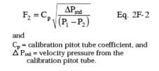
See Figure 2F-15 for an example F2 versus pitch angle
calibration curve.
10.6.4 Connect
the tested probe and calibration pitot probe to their respective
pressure-measuring devices. Zero the pressure-measuring devices. Inspect and
leak-check all pitot lines; repair or replace, if necessary. Turn on the fan,
and allow the wind tunnel air flow to stabilize at the first of the two
selected nominal velocity settings.
10.6.5
Position the calibration pitot tube at its measurement location (determined as outlined
in section 6.11.4.3), and align the tube so that its tip is pointed directly
into the flow. Ensure that the entry port surrounding the tube is properly
sealed. The calibration pitot tube may either remain in the wind tunnel
throughout the calibration, or be removed from the wind tunnel while
measurements are taken with the probe being calibrated.
10.6.6 Set up
the pitch protractor plate on the tested probe’s entry port to establish the
pitch angle positions of the probe to within ±2°.
10.6.7 Check
the zero setting of each pressure-measuring device.
10.6.8 Insert
the tested probe into the wind tunnel and align it so that its P1 pressure port
is pointed directly into the flow and is positioned within the calibration
location (as defined in section 3.20). Secure the probe at the 0° pitch angle
position. Ensure that the entry port surrounding the probe is properly sealed.
10.6.9 Read
the differential pressure from the calibration pitot tube (DeltaPstd), and
record its value. Read the barometric pressure to within ±2.5 mm Hg (±0.1 in.
Hg) and the temperature in the wind tunnel to within 0.6°C (1°F). Record these
values on a data form similar to Table 2F-8.
10.6.10 After
the tested probe’s differential pressure gauges have had sufficient time to
stabilize, yaw null the probe, then obtain differential pressure readings for
(P1-P2) and (P4-P5). Record the yaw angle and differential pressure readings.
After taking these readings, ensure that the tested probe has remained at the
yaw-null position.
10.6.11
Either take paired differential pressure measurements with both the calibration
pitot tube and tested probe (according to sections 10.6.9 and 10.6.10) or take
readings only with the tested probe (according to section 10.6.10) in 5°
increments over the pitch-angle range for which the probe is to be calibrated.
The calibration pitch-angle range shall be symmetric around 0° and shall exceed
the largest pitch angle expected in the field by 5°. At a minimum, probes shall
be calibrated over the range of -15° to +15°. If paired calibration pitot tube
and tested probe measurements are not taken at each pitch angle setting, the
differential pressure from the calibration pitot tube shall be read, at a
minimum, before taking the tested probe’s differential pressure reading at the
first pitch angle setting and after taking the tested probe’s differential
pressure readings at the last pitch angle setting in each replicate.
10.6.12
Perform a second replicate of the procedures in sections 10.6.5 through 10.6.11
at the same nominal velocity setting.
10.6.13 For
each replicate, calculate the F1 and F2 values at each pitch angle. At each
pitch angle, calculate the percent difference between the two F2 values using
Equation 2F-3.
![]()
If the percent
difference is less than or equal to 2 percent, calculate an average F1 value
and an average F2 value at that pitch angle. If the percent difference is
greater than 2 percent and less than or equal to 5 percent, perform a third
repetition at that angle and calculate an average F1 value and an average F2
value using all three repetitions. If the percent difference is greater than 5
percent, perform four additional repetitions at that angle and calculate an
average F1 value and an average F2 value using all six repetitions. When
additional repetitions are required at any pitch angle, move the probe by at
least 5° and then return to the specified pitch angle before taking the next
measurement. Record the average values on a form similar to Table
2F-9.
10.6.14 Repeat
the calibration procedures in sections 10.6.5 through 10.6.13 at the second
selected nominal wind tunnel velocity setting.
10.6.15
Velocity drift check. The following check shall be performed, except when
paired calibration pitot tube and tested probe pressure measurements are taken
at each pitch angle setting. At each velocity setting, calculate the percent
difference between consecutive differential pressure measurements made with the
calibration pitot tube. If a measurement differs from the previous measurement
by more than 2 percent or 0.25 mm H2O (0.01 in. H2O), whichever is less
restrictive, the calibration data collected between these calibration pitot
tube measurements may not be used, and the measurements shall be repeated.
10.6.16
Compare the averaged F2 coefficients obtained from the calibrations at the two
selected nominal velocities, as follows. At each pitch angle setting, use
Equation 2F-3 to calculate the difference between the corresponding average F2
values at the two calibration velocities. At each pitch angle in the -15° to
+15° range, the percent difference between the average F2 values shall not
exceed 3.0 percent. For pitch angles outside this range (i.e., less than -15°0
and greater than +15°), the percent difference shall not exceed 5.0 percent.
10.6.16.1 If
the applicable specification in section 10.6.16 is met at each pitch angle
setting, average the results obtained at the two nominal calibration velocities
to produce a calibration record of F1 and F2 at each pitch angle tested. Record
these values on a form similar to Table 2F-9. From these values, generate one
calibration curve representing F1 versus pitch angle and a second curve
representing F2 versus pitch angle. Computer spreadsheet programs may be used
to graph the calibration data and to develop polynomial equations that can be
used to calculate pitch angles and axial velocities.
10.6.16.2 If
the applicable specification in section 10.6.16 is exceeded at any pitch angle
setting, the probe shall not be used unless: (1) the calibration is repeated at
that pitch angle and acceptable results are obtained or (2) values of F1 and F2
are obtained at two nominal velocities for which the specifications in section
10.6.16 are met across the entire pitch angle range.
10.7 Recalibration.
Recalibrate
the probe using the procedures in section 10 either within 12 months of its
first field use after its most recent calibration or after 10 field tests (as
defined in section 3.4), whichever occurs later. In addition, whenever there is
visible damage to the 3-D head, the probe shall be recalibrated before it is
used again.
10.8 Calibration of pressure-measuring devices used in field tests.
Before its
initial use in a field test, calibrate each pressure-measuring device (except
those used exclusively for yaw nulling) using the three-point calibration
procedure described in section 10.3.3. The device shall be recalibrated
according to the procedure in section 10.3.3 no later than 90 days after its
first field use following its most recent calibration. At the discretion of the
tester, more frequent calibrations (e.g., after a field test) may be performed.
No adjustments, other than adjustments to the zero setting, shall be made to
the device between calibrations.
10.8.1 Post-test calibration check.
A single-point
calibration check shall be performed on each pressure-measuring device after
completion of each field test. At the discretion of the tester, more frequent
single-point calibration checks (e.g., after one or more field test runs) may
be performed. It is recommended that the post-test check be performed before
leaving the field test site. The check shall be performed at a pressure between
50 and 90 percent of full scale by taking a common pressure reading with the
tested device and a reference pressure-measuring device (as described in
section 6.4.4) or by challenging the tested device with a reference pressure
source (as described in section 6.4.4) or by performing an equivalent check
using a reference device approved by the Administrator.
10.8.2 Acceptance criterion.
At the
selected pressure setting, the pressure readings made using the reference
device and the tested device shall agree to within 3 percent of full scale of
the tested device or 0.8 mm H2O (0.03 in. H2O), whichever is less restrictive.
If this specification is met, the test data collected during the field test are
valid. If the specification is not met, all test data collected since the last
successful calibration or calibration check are invalid and shall be repeated
using a pressure-measuring device with a current, valid calibration. Any device
that fails the calibration check shall not be used in a field test until a
successful recalibration is performed according to the procedures in section
10.3.3.
10.9 Temperature Gauges. Same as Method 2, section 4.3.
The
alternative thermocouple calibration procedures outlined in Emission
Measurement Center (EMC) Approved Alternative Method (ALT-011) ‘‘Alternative
Method 2 Thermocouple Calibration Procedure’’ may be performed. Temperature
gauges shall be calibrated no more than 30 days prior to the start of a field
test or series of field tests and recalibrated no more than 30 days after
completion of a field test or series of field tests.
10.10 Barometer.
Same as Method
2, section 4.4. The barometer shall be calibrated no more than 30 days prior to
the start of a field test or series of field tests.
11.0 Analytical Procedure
Sample collection
and analysis are concurrent for this method (see section 8.0).
12.0 Data Analysis and Calculations
These
calculations use the measured yaw angle, derived pitch angle, and the
differential pressure and temperature measurements at individual traverse
points to derive the axial flue gas velocity (va (avg)) at each of those
points. The axial velocity values at all traverse points that comprise a full
stack or duct traverse are then averaged to obtain the average axial flue gas
velocity (va (avg)). Round off figures only in the final calculation of
reported values.
12.1 Nomenclature
A =
Cross-sectional area of stack or duct, m 2 (ft 2).
Bws = Water
vapor in the gas stream (from Method 4 or alternative), proportion by volume.
Kp =
Conversion factor (a constant),
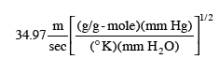
for the metric
system, and
![]()
for the
English system.
Md = Molecular
weight of stack or duct gas, dry basis (see section 8.13), g/g-mole (lb/
lb-mole).
Ms = Molecular
weight of stack or duct gas, wet basis, g/g-mole (lb/lb-mole).
![]()
Pbar =
Barometric pressure at measurement site, mm Hg (in. Hg).
Pg = Stack or
duct static pressure, mm H2O (in. H2O).
Ps = Absolute
stack or duct pressure, mm Hg (in. Hg),
![]()
Pstd =
Standard absolute pressure, 760 mm Hg (29.92 in. Hg).
13.6 =
Conversion from mm H2O (in. H2O) to mm Hg (in. Hg).
Qsd = Average
dry-basis volumetric stack or duct gas flow rate corrected to standard
conditions, dscm/hr (dscf/hr).
Qsw = Average
wet-basis volumetric stack or duct gas flow rate corrected to standard
conditions,
wscm/hr (wscf/hr).
Ts(avg) =
Average absolute stack or duct gas temperature across all traverse points.
ts(i) = Stack
or duct gas temperature, C (F), at traverse point i.
Ts(i) =
Absolute stack or duct gas temperature, K (R), at traverse point i,
![]()
for the metric
system, and
![]()
Ts(i) = 460 +
ts(i) Eq. 2F-7 for the English system.
Tstd =
Standard absolute temperature, 293°K (528°R).
F1(i) = Pitch
angle ratio, applicable at traverse point i, dimensionless.
F2(i) = 3-D probe
velocity calibration coefficient, applicable at traverse point i,
dimensionless.
(P4-P5)i =
Pitch differential pressure of stack or duct gas flow, mm H2O (in. H2O), at
traverse point
i.
(P1-P2)i =
Velocity head (differential pressure) of stack or duct gas flow, mm H2O (in.
H2O), at traverse point i.
va(i) =
Reported stack or duct gas axial velocity, m/sec (ft/sec), at traverse point i.
va(avg) =
Average stack or duct gas axial velocity, m/sec (ft/sec), across all traverse
points.
3,600 =
Conversion factor, sec/hr.
18.0 =
Molecular weight of water, g/g-mole (lb/lb-mole).
0y(i) =
Yaw angle, degrees, at traverse point i.
0p(i) =
Pitch angle, degrees, at traverse point i.
n = Number of
traverse points.
12.2 Traverse Point Velocity Calculations.
Perform the
following calculations from the measurements obtained at each traverse point.
12.2.1 Selection of calibration curves.
Select
calibration curves as described in section 10.6.1.
12.2.2 Traverse point pitch angle ratio.
Use Equation
2F-1, as described in section 10.6.2, to calculate the pitch angle ratio,
F1(i), at each traverse point.
12.2.3 Pitch angle.
Use the pitch
angle ratio, F1(i), to derive the pitch angle, 0p(i), at traverse point
i from the F1 versus pitch angle calibration curve generated under section
10.6.16.1.
12.2.4 Velocity calibration coefficient.
Use the pitch
angle, 0p(i), to obtain the probe velocity calibration coefficient,
F2(i), at traverse point i from the ‘‘velocity pressure calibration curve,’’ i.e.,
the F2 versus pitch angle calibration curve generated under section 10.6.16.1.
12.2.5 Axial velocity.
Use the
following equation to calculate the axial velocity, va(i), from the
differential pressure (P1-P2)i and yaw angle, 0y(i), measured at traverse point
i and the previously calculated values for the velocity calibration
coefficient, F2(i), absolute stack or duct standard temperature, Ts(i),
absolute stack or duct pressure, Ps, molecular weight, Ms, and pitch angle, ‘‘0p(i).
![]()
12.2.6 Handling multiple measurements at a traverse point.
For pressure
or temperature devices that take multiple measurements at a traverse point, the
multiple measurements (or where applicable, their square roots) may first be
averaged and the resulting average values used in the equations above.
Alternatively, the individual measurements may be used in the equations above
and the resulting multiple calculated values may then be averaged to obtain a
single traverse point value. With either approach, all of the individual
measurements recorded at a traverse point must be used in calculating the
applicable traverse point value.
12.3 Average Axial Velocity in Stack or Duct.
Use the
reported traverse point axial velocity in the following equation.
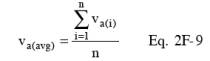
12.4 Acceptability of Results.
The test
results are acceptable and the calculated value of va(avg) may be reported as
the average axial velocity for the test run if the conditions in either section
12.4.1 or 12.4.2 are met.
12.4.1 The calibration
curves were generated at nominal velocities of 18.3 m/sec and 27.4 m/sec (60
ft/sec and 90 ft/sec).
12.4.2 The
calibration curves were generated at nominal velocities other than 18.3 m/sec
and 27.4 m/sec (60 ft/sec and 90 ft/sec), and the value of va(avg) obtained
using Equation 2F-9 is less than or equal to at least one of the nominal
velocities used to derive the F1 and F2 calibration curves.
12.4.3 If the
conditions in neither section 12.4.1 nor section 12.4.2 are met, the test
results obtained in Equation 2F-9 are not acceptable, and the steps in sections
12.2 and 12.3 must be repeated using a set of F1 and F2 calibration curves that
satisfies the conditions specified in section 12.4.1 or 12.4.2.
12.5 Average Gas Wet Volumetric Flow Rate in Stack or Duct.
Use the
following equation to compute the average volumetric flow rate on a wet basis.
![]()
12.6 Average Gas Dry Volumetric Flow Rate in Stack or Duct.
Use the
following equation to compute the average volumetric flow rate on a dry basis.
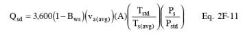
13.0 Method Performance. [Reserved]
14.0 Pollution Prevention. [Reserved]
15.0 Waste Management. [Reserved]
16.0 Reporting
16.1 Field Test Reports.
Field test
reports shall be submitted to the Agency according to applicable regulatory
requirements. Field test reports should, at a minimum, include the following
elements.
16.1.1 Description of the source.
This should
include the name and location of the test site, descriptions of the process
tested, a description of the combustion source, an accurate diagram of stack or
duct cross-sectional area at the test site showing the dimensions of the stack
or duct, the location of the test ports, and traverse point locations and
identification numbers or codes. It should also include a description and
diagram of the stack or duct layout, showing the distance of the test location
from the nearest upstream and downstream disturbances and all structural
elements (including breachings, baffles, fans, straighteners, etc.) affecting
the flow pattern. If the source and test location descriptions have been
previously submitted to the Agency in a document (e.g., a monitoring plan or
test plan), referencing the document in lieu of including this information in
the field test report is acceptable.
16.1.2 Field test procedures.
These should
include a description of test equipment and test procedures. Testing
conventions, such as traverse point numbering and measurement sequence (e.g., sampling
from center to wall, or wall to center), should be clearly stated. Test port
identification and directional reference for each test port should be included
on the appropriate field test data sheets.
16.1.3 Field test data.
16.1.3.1
Summary of results. This summary should include the dates and times of testing
and the average axial gas velocity and the average flue gas volumetric flow
results for each run and tested condition.
16.1.3.2 Test
data. The following values for each traverse point should be recorded and
reported:
(a) P1-P2 and
P4-P5 differential pressures
(b) Stack or
duct gas temperature at traverse point i (ts(i))
(c) Absolute
stack or duct gas temperature at traverse point i (Ts(i))
(d) Yaw angle
at each traverse point i (0y(i))
(e) Pitch
angle at each traverse point i (0p(i))
(f) Stack or
duct gas axial velocity at traverse point i (va(i))
16.1.3.3 The
following values should be reported once per run:
(a) Water
vapor in the gas stream (from Method 4 or alternative), proportion by volume
(Bws), measured at the frequency specified in the applicable regulation
(b) Molecular
weight of stack or duct gas, dry basis (Md)
(c) Molecular
weight of stack or duct gas, wet basis (Ms)
(d) Stack or
duct static pressure (Pg)
(e) Absolute stack
or duct pressure (Ps)
(f) Carbon
dioxide concentration in the flue gas, dry basis (0⁄0d CO2)
(g) Oxygen
concentration in the flue gas, dry basis (0⁄0d O2)
(h) Average
axial stack or duct gas velocity (va(avg)) across all traverse points
(i) Gas volumetric
flow rate corrected to standard conditions, dry or wet basis as required by the
applicable regulation (Qsd or Qsw)
16.1.3.4 The
following should be reported once per complete set of test runs:
(a) Cross-sectional
area of stack or duct at the test location (A)
(b)
Measurement system response time (sec)
(c) Barometric
pressure at measurement site (Pbar)
16.1.4 Calibration data.
The field test
report should include calibration data for all probes and test equipment used
in the field test. At a minimum, the probe calibration data reported to the
Agency should include the following:
(a) Date of
calibration
(b) Probe type
(c) Probe
identification number(s) or code(s)
(d) Probe
inspection sheets
(e) Pressure
measurements and intermediate calculations of F1 and F2 at each pitch angle
used to obtain calibration curves in accordance with section 10.6 of this
method
(f)
Calibration curves (in graphic or equation format) obtained in accordance with sections 10.6.11 of this method
(g)
Description and diagram of wind tunnel used for the calibration, including
dimensions of cross-sectional area and position and size of the test section
(h)
Documentation of wind tunnel qualification tests performed in accordance with
section 10.1 of this method
16.1.5 Quality Assurance.
Specific
quality assurance and quality control procedures used during the test should be
described.
17.0 Bibliography
(1) 40 CFR
Part 60, Appendix A, Method 1 - Sample and velocity traverses for stationary
sources.
(2) 40 CFR
Part 60, Appendix A, Method 2H - Determination of stack gas velocity taking
into account velocity decay near the stack wall.
(3) 40 CFR
Part 60, Appendix A, Method 2 - Determination of stack gas velocity and
volumetric flow rate (Type S pitot tube).
(4) 40 CFR
Part 60, Appendix A, Method 3 - Gas analysis for carbon dioxide, oxygen, excess
air, and dry molecular weight.
(5) 40 CFR
Part 60, Appendix A, Method 3A - Determination of oxygen and carbon dioxide
concentrations in emissions from stationary sources (instrumental analyzer
procedure).
(6) 40 CFR
Part 60, Appendix A, Method 4 - Determination of moisture content in stack
gases.
(7) Emission
Measurement Center (EMC) Approved Alternative Method (ALT-011) ‘‘Alternative
Method 2 Thermocouple Calibration Procedure.’’
(8) Electric
Power Research Institute, Interim Report EPRI TR-106698, ‘‘Flue Gas Flow Rate
Measurement Errors,’’ June 1996.
(9) Electric Power
Research Institute, Final Report EPRI TR-108110, ‘‘Evaluation of Heat Rate
Discrepancy from Continuous Emission Monitoring Systems,’’ August 1997.
(10) Fossil
Energy Research Corporation, Final Report, ‘‘Velocity Probe Tests in Nonaxial
Flow Fields,’’ November 1998, Prepared for the U.S. Environmental Protection
Agency.
(11) Fossil
Energy Research Corporation, ‘‘Additional Swirl Tunnel Tests: E-DAT and T-DAT
Probes,’’ February 24, 1999, Technical Memorandum Prepared for U.S.
Environmental Protection Agency, P.O. No.
7W-1193-NALX.
(12)
Massachusetts Institute of Technology, Report WBWT-TR-1317, ‘‘Calibration of
Eight Wind Speed Probes Over a Reynolds Number Range of 46,000 to 725,000 Per
Foot, Text and Summary Plots,’’ Plus appendices, October 15, 1998, Prepared for
The Cadmus Group, Inc.
(13) National
Institute of Standards and Technology, Special Publication 250, ‘‘NIST
Calibration Services Users Guide 1991,’’ Revised October 1991, U.S. Department
of Commerce, p. 2.
(14) National
Institute of Standards and Technology, 1998, ‘‘Report of Special Test of Air
Speed Instrumentation, Four Prandtl Probes, Four S-Type Probes, Four French
Probes, Four Modified Kiel Probes,’’ Prepared for the U.S. Environmental
Protection Agency under IAG #DW13938432-01-0.
(15) National
Institute of Standards and Technology, 1998, ‘‘Report of Special Test of Air
Speed Instrumentation, Five Autoprobes,’’ Prepared for the U.S. Environmental
Protection Agency under IAG #DW13938432-01-0.
(16) National
Institute of Standards and Technology, 1998, ‘‘Report of Special Test of Air
Speed Instrumentation, Eight Spherical Probes,’’ Prepared for the U.S.
Environmental Protection Agency under IAG #DW13938432-01-0.
(17) National
Institute of Standards and Technology, 1998, ‘‘Report of Special Test of Air
Speed Instrumentation, Four DAT Probes,’’ Prepared for the U.S. Environmental
Protection Agency under IAG #DW13938432-01-0.
(18) Norfleet,
S.K., ‘‘An Evaluation of Wall Effects on Stack Flow Velocities and Related
Overestimation Bias in EPA’s Stack Flow Reference Methods,’’ EPRI CEMS User’s
Group Meeting, New Orleans, Louisiana, May 13-15, 1998.
(19) Page,
J.J., E.A. Potts, and R.T. Shigehara, ‘‘3-D Pitot Tube Calibration Study,’’ EPA
Contract No. 68-D1-0009, Work Assignment No. I-121, March 11, 1993.
(20)
Shigehara, R.T., W.F. Todd, and W.S. Smith, ‘‘Significance of Errors in Stack
Sampling Measurements,’’ Presented at the Annual Meeting of the Air Pollution
Control Association, St. Louis, Missouri, June 14-19, 1970.
(21) The
Cadmus Group, Inc., May 1999, ‘‘EPA Flow Reference Method Testing and Analysis:
Findings Report,’’ EPA/430-R-99-009.
(22) The
Cadmus Group, Inc., 1998, ‘‘EPA Flow Reference Method Testing and Analysis:
Data Report, Texas Utilities, DeCordova Steam Electric Station, Volume I: Test
Description and Appendix A (Data Distribution Package),’’ EPA/430-R-98-015a.
(23) The
Cadmus Group, Inc., 1998, ‘‘EPA Flow Reference Method Testing and Analysis:
Data Report, Texas Utilities, Lake Hubbard Steam Electric Station, Volume I:
Test Description and Appendix A (Data Distribution Package),’’
EPA/430-R-98-017a.
(24) The
Cadmus Group, Inc., 1998, ‘‘EPA Flow Reference Method Testing and Analysis:
Data Report, Pennsylvania Electric Co., G.P.U. Genco Homer City Station: Unit
1, Volume I: Test Description and Appendix A (Data Distribution Package),’’
EPA/430-R-98-018a.
(25) The
Cadmus Group, Inc., 1997, ‘‘EPA Flow Reference Method Testing and Analysis:
Wind Tunnel Experimental Results,’’ EPA/430-R-97-013.
18.0 Annexes
Annex A, C,
and D describe recommended procedures for meeting certain provisions in
sections 8.3, 10.4, and 10.5 of this method. Annex B describes procedures to be
followed when using the protractor wheel and pointer assembly to measure yaw
angles, as provided under section 8.9.1.
18.1 Annex A - Rotational Position Check.
The following
are recommended procedures that may be used to satisfy the rotational position
check requirements of section 8.3 of this method and to determine the
angle-measuring device rotational offset (RADO).
18.1.1 Rotational position check with probe outside stack.
Where physical
constraints at the sampling location allow full assembly of the probe outside
the stack and insertion into the test port, the following procedures should be
performed before the start of testing. Two angle-measuring devices that meet
the specifications in section 6.2.1 or 6.2.3 are required for the rotational
position check. An angle-measuring device whose position can be independently
adjusted (e.g., by means of a set screw) after being locked into position on
the probe sheath shall not be used for this check unless the independent
adjustment is set so that the device performs exactly like a device without the
capability for independent adjustment. That is, when aligned on the probe such
a device must give the same reading as a device that does not have the
capability of being independently adjusted. With the fully assembled probe
(including probe shaft extensions, if any) secured in a horizontal position,
affix one yaw angle-measuring device to the probe sheath and lock it into
position on the reference scribe line specified in section 6.1.6.1. Position
the second angle-measuring device using the procedure in section 18.1.1.1 or
18.1.1.2.
18.1.1.1
Marking procedure. The procedures in this section should be performed at each
location on the fully assembled probe where the yaw angle-measuring device will
be mounted during the velocity traverse. Place the second yaw angle-measuring
device on the main probe sheath (or extension) at the position where a yaw
angle will be measured during the velocity traverse. Adjust the position of the
second angle-measuring device until it indicates the same angle (±1°) as the
reference device, and affix the second device to the probe sheath (or extension).
Record the angles indicated by the two angle-measuring devices on a form
similar to Table 2F-2. In this position, the second
angle-measuring device is considered to be properly positioned for yaw angle
measurement. Make a mark, no wider than 1.6 mm (1/16 in.), on the probe sheath
(or extension), such that the yaw angle-measuring device can be re-affixed at
this same properly aligned position during the velocity traverse.
18.1.1.2
Procedure for probe extensions with scribe lines. If, during a velocity
traverse the angle-measuring device will be affixed to a probe extension having
a scribe line as specified in section 6.1.6.2, the following procedure may be
used to align the extension’s scribe line with the reference scribe line
instead of marking the extension as described in section 18.1.1.1. Attach the
probe extension to the main probe. Align and lock the second angle-measuring
device on the probe extension’s scribe line. Then, rotate the extension until
both measuring devices indicate the same angle (±1°). Lock the extension at
this rotational position. Record the angles indicated by the two
angle-measuring devices on a form similar to Table 2F-2. An angle-measuring
device may be aligned at any position on this scribe line during the velocity
traverse, if the scribe line meets the alignment specification in section
6.1.6.3.
18.1.1.3 Post-test rotational position check. If the fully
assembled probe includes one or more extensions, the following check should be
performed immediately after the completion of a velocity traverse. At the
discretion of the tester, additional checks may be conducted after completion
of testing at any sample port. Without altering the alignment of any of the
components of the probe assembly used in the velocity traverse, secure the
fully assembled probe in a horizontal position. Affix an angle-measuring device
at the reference scribe line specified in section 6.1.6.1. Use the other
angle-measuring device to check the angle at each location where the device was
checked prior to testing. Record the readings from the two angle-measuring
devices.
18.1.2 Rotational position check with probe in stack.
This section
applies only to probes that, due to physical constraints, cannot be inserted
into the test port as fully assembled with all necessary extensions needed to
reach the inner-most traverse point(s).
18.1.2.1
Perform the out-of-stack procedure in section 18.1.1 on the main probe and any
attached extensions that will be initially inserted into the test port.
18.1.2.2 Use
the following procedures to perform additional rotational position check(s)
with the probe in the stack, each time a probe extension is added. Two
angle-measuring devices are required. The first of these is the device that was
used to measure yaw angles at the preceding traverse point, left in its
properly aligned measurement position. The second angle-measuring device is
positioned on the added probe extension. Use the applicable procedures in
section 18.1.1.1 or 18.1.1.2 to align, adjust, lock, and mark (if necessary)
the position of the second angle-measuring device to within ±1° of the first
device. Record the readings of the two devices on a form similar to Table 2F-2.
18.1.2.3 The
procedure in section 18.1.2.2 should be performed at the first port where
measurements are taken. The procedure should be repeated each time a probe
extension is re-attached at a subsequent port, unless the probe extensions are
designed to be locked into a mechanically fixed rotational position (e.g., through
use of interlocking grooves), which can be reproduced from port to port as
specified in section 8.3.5.2.
18.2 Annex B - Angle Measurement Protocol for Protractor Wheel and Pointer Device.
The following
procedure shall be used when a protractor wheel and pointer assembly, such as
the one described in section 6.2.2 and illustrated in Figure
2F-7 is used to measure the yaw angle of flow. With each move to a new
traverse point, unlock, re-align, and re-lock the probe, angle-pointer collar,
and protractor wheel to each other. At each such move, particular attention is
required to ensure that the scribe line on the angle pointer collar is either
aligned with the reference scribe line on the main probe sheath or is at the
rotational offset position established under section 8.3.1. The procedure
consists of the following steps:
18.2.1 Affix a
protractor wheel to the entry port for the test probe in the stack or duct.
18.2.2 Orient
the protractor wheel so that the 0° mark corresponds to the longitudinal axis
of the stack or duct. For stacks, vertical ducts, or ports on the side of
horizontal ducts, use a digital inclinometer meeting the specifications in
section 6.2.1 to locate the 0° orientation. For ports on the top or bottom of horizontal
ducts, identify the longitudinal axis at each test port and permanently mark
the duct to indicate the 0° orientation. Once the protractor wheel is properly
aligned, lock it into position on the test port.
18.2.3 Move
the pointer assembly along the probe sheath to the position needed to take
measurements at the first traverse point. Align the scribe line on the pointer
collar with the reference scribe line or at the rotational offset position
established under section 8.3.1. Maintaining this rotational alignment, lock
the pointer device onto the probe sheath. Insert the probe into the entry port
to the depth needed to take measurements at the first traverse point.
18.2.4 Perform
the yaw angle determination as specified in sections 8.9.3 and 8.9.4 and record
the angle as shown by the pointer on the protractor wheel. Then, take velocity
pressure and temperature measurements in accordance with the procedure in
section 8.9.5. Perform the alignment check described in section 8.9.6.
18.2.5 After
taking velocity pressure measurements at that traverse point, unlock the probe
from the collar and slide the probe through the collar to the depth needed to
reach the next traverse point.
18.2.6 Align
the scribe line on the pointer collar with the reference scribe line on the
main probe or at the rotational offset position established under section
8.3.1. Lock the collar onto the probe.
18.2.7 Repeat
the steps in sections 18.2.4 through 18.2.6 at the remaining traverse points
accessed from the current stack or duct entry port.
18.2.8 After
completing the measurement at the last traverse point accessed from a port,
verify that the orientation of the protractor wheel on the test port has not
changed over the course of the traverse at that port. For stacks, vertical
ducts, or ports on the side of horizontal ducts, use a digital inclinometer
meeting the specifications in section 6.2.1 to check the rotational position of
the 0° mark on the protractor wheel. For ports on the top or bottom of
horizontal ducts, observe the alignment of the angle wheel 0° mark relative to
the permanent 0° mark on the duct at that test port. If these observed
comparisons exceed ±2° of 0°, all angle and pressure measurements taken at that
port since the protractor wheel was last locked into position on the port shall
be repeated.
18.2.9 Move to
the next stack or duct entry port and repeat the steps in sections
18.2.1 through
18.2.8.
18.3 Annex C - Guideline for Reference Scribe Line Placement.
Use of the
following guideline is recommended to satisfy the requirements of section 10.4
of this method. The rotational position of the reference scribe line should be
either 90° or 180° from the probe’s impact pressure port.
18.4 Annex D - Determination of Reference Scribe Line Rotational Offset.
The following
procedures are recommended for determining the magnitude and sign of a probe’s
reference scribe line rotational offset, RSLO. Separate procedures are provided
for two types of angle-measuring devices: digital inclinometers and protractor
wheel and pointer assemblies.
18.4.1 Perform
the following procedures on the main probe with all devices that will be
attached to the main probe in the field [such as thermocouples or resistance
temperature detectors (RTDs)] that may affect the flow around the probe head.
Probe shaft extensions that do not affect flow around the probe head need not
be attached during calibration.
18.4.2 The
procedures below assume that the wind tunnel duct used for probe calibration is
horizontal and that the flow in the calibration wind tunnel is axial as
determined by the axial flow verification check described in section 10.1.2.
Angle-measuring devices are assumed to display angles in alternating 0° to 90°
and 90° to 0° intervals. If angle-measuring devices with other readout
conventions are used or if other calibration wind tunnel duct configurations
are used, make the appropriate calculational corrections.
18.4.2.1
Position the angle-measuring device in accordance with one of the following
procedures.
18.4.2.1.1 If
using a digital inclinometer, affix the calibrated digital inclinometer to the
probe. If the digital inclinometer can be independently adjusted after being
locked into position on the probe sheath (e.g., by means of a set screw), the
independent adjustment must be set so that the device performs exactly like a
device without the capability for independent adjustment. That is, when aligned
on the probe the device must give the same readings as a device that does not
have the capability of being independently adjusted. Either align it directly
on the reference scribe line or on a mark aligned with the scribe line
determined according to the procedures in section 18.1.1.1. Maintaining this
rotational alignment, lock the digital inclinometer onto the probe sheath.
18.4.2.1.2 If
using a protractor wheel and pointer device, orient the protractor wheel on the
test port so that the 0° mark is aligned with the longitudinal axis of the wind
tunnel duct. Maintaining this alignment, lock the wheel into place on the wind
tunnel test port. Align the scribe line on the pointer collar with the
reference scribe line or with a mark aligned with the reference scribe line, as
determined under section 18.1.1.1. Maintaining this rotational alignment, lock
the pointer device onto the probe sheath.
18.4.2.2 Zero
the pressure-measuring device used for yaw nulling.
18.4.2.3
Insert the probe assembly into the wind tunnel through the entry port,
positioning the probe’s impact port at the calibration location. Check the
responsiveness of the pressure-measuring device to probe rotation, taking
corrective action if the response is unacceptable.
18.4.2.4
Ensure that the probe is in a horizontal position using a carpenter’s level.
18.4.2.5
Rotate the probe either clockwise or counterclockwise until a yaw null (P2=P3)
is obtained.
18.4.2.6 Read
and record the value of Tnull, the angle indicated by the angle-measuring
device at the yaw-null position. Record the angle reading on a form similar to
Table 2F-6. Do not associate an algebraic sign with this reading.
18.4.2.7
Determine the magnitude and algebraic sign of the reference scribe line
rotational offset, RSLO. The magnitude of RSLO will be equal to either Tnull or
(90°´Tnull), depending on the angle-measuring device used. (See Table 2F-7 for
a summary.) The algebraic sign of RSLO will either be positive, if the
rotational position of the reference scribe line is clockwise, or negative, if
counter-clockwise with respect to the probe’s yaw-null position. Figure 2F-13illustrates how the magnitude and sign of
RSLO are determined.
18.4.2.8
Perform the steps in sections
18.4.2.3
through 18.4.2.7 twice at each of the two calibration velocities selected for
the probe under section 10.6. Record the values of RSLO in a form similar to Table 2F-6.
18.4.2.9 The
average of all RSLO values is the reference scribe line rotational offset for
the probe.
Figure
2F-1. Illustration of yaw and
pitch planes in stack or duct.
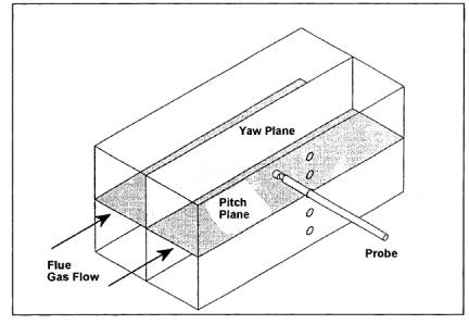
Figure
2F-2. Illustration of probe
rotation representing positive and negative yaw
angles.
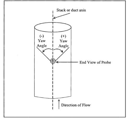
Figure
2F-3. Illustration of a five-hole prism-shaped
(DAT) probe.
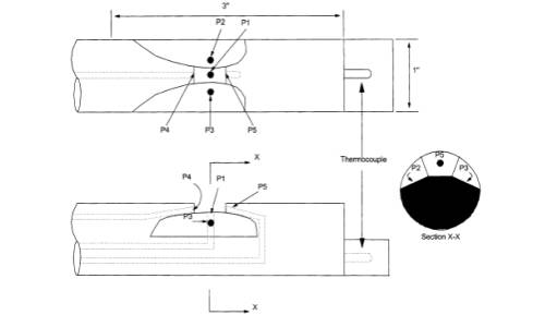
Figure
2F-4. Illustration of front and
side view of spherical probe.
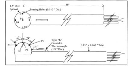
Figure
2F-5. Example bushing sleeve.
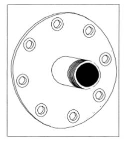
Figure 2F-6.
Rotational position collar block.
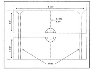
Figure
2F-7. Yaw angle protractor wheel and
poister.
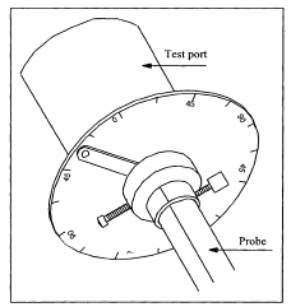
Figure
2F-8. Pitch angle protractor
plate.
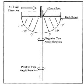
Figure
2F-9. Elements in horizontal
straightness test using trigonometry.
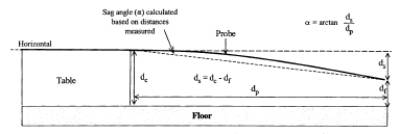
Figure
2F-10. Sign convention for the
measured angle (0) when the
probe impact port is pointed directly
into the flow.
The angle 0 is positive when the
probe’s impact pressure
port is oriented in a clockwise rotational position
relative to the stack or duct axis, as shown below , and
negative for a counterclockwise
orientation.
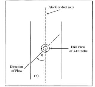
Figure
2F-11. Wedge probe used for axial
flow verification.
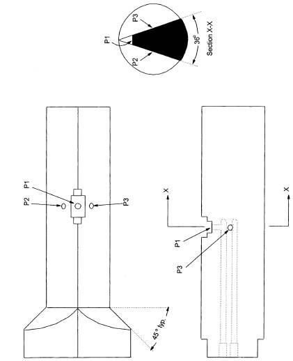
Figure
2F-12. Triangular block used for
digital inclinometer calibration.
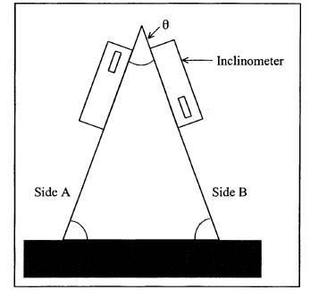
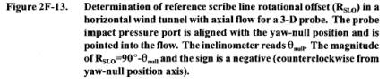
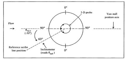
Figure
2F-14. Example F1 calibration
curve for DAT probe.
Figure
2F-15. Example F2 calibration
curve for DAT probe.
Table
2F-1. 3-D Probe Inspection Sheet
Table 2F-2. Rotational Position Check
Table 2F-3. Example EPA Method 2F Field Data Form
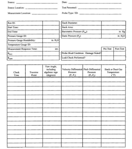
Table 2F-4. Wind Tunnel Velocity Pressure Cross-Check
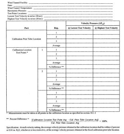
Table 2F-5. Wind Tunnel Axial Flow Verification
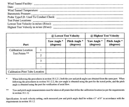
Table 2F-6. Yaw Angle Calibration.
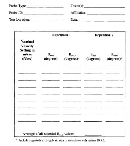
Table 2F-7. Determining the Magnitude of Reference Scribe Line Offset.
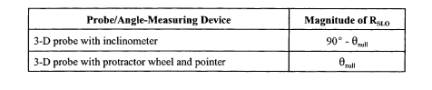
Table 2F-8. Wind Tunnel Calibration of Three-Dimensional Probe
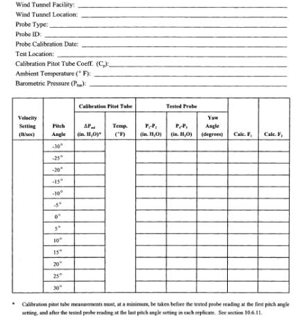
Table 2F-9. Calibration Log for Three-Dimensional Probe.