Method 3A - Determination of Oxygen and Carbon Dioxide Concentrations in Emissions from Stationary Sources
(Instrumental
Analyzer Procedure)
1.
APPLICABILITY AND PRINCIPLE
4. MEASUREMENT SYSTEM
PERFORMANCE SPECIFICATIONS
6. MEASUREMENT SYSTEM
PERFORMANCE TEST PROCEDURES
6.1 Calibration
Concentration Verification.
7.1 Selection of
Sampling Site and Sampling Points.
7.3 Zero and
Calibration Drift Test.
1. APPLICABILITY AND PRINCIPLE
1.1Applicability.
This
method is applicable to the determination of oxygen (O 2) and carbon dioxide (C2O ) concentrations in
emissions from stationary sources only when specified within the regulations.
1.2 Principle.
A
sample is continuously extracted from the effluent stream: a portion of the
sample stream is conveyed to an instrumental analyzer(s) for determination of O2 and CO2 concentration(s).
Performance specifications and test procedures are provided to ensure reliable
data.
2. RANGE AND SENSITIVITY
Same
as in Method 6C, Sections 2.1 and 2.2,
except that the span of the monitoring system shall be selected such that the
average O2 or C20 concentration is not
less than 20 percent of the span.
3. DEFINITIONS
3.1 Measurement System.
The
total equipment required for the determination of the O2 or CO2 concentration. The
measurement system consists of the same major subsystems as defined in Method 6C, Sections 3.1.1, 3.1.2, and 3.1.3.
3.2 Span, Calibration Gas, Analyzer Calibration Error, Sampling System Bias, Zero Drift, Calibration Drift, Response Time, and Calibration Curve.
Same
as in Method 6C, Sections 3.2 through 3.8,
and 3.10.
3.3 Interference Response.
The
output response of the measurement system to a component in the sample gas,
other than the gas component being measured.
4. MEASUREMENT SYSTEM PERFORMANCE SPECIFICATIONS
Same
as in Method 6C, Sections 4.1 through 4.4.
5. APPARATUS AND REAGENTS
5.1 Measurement System.
Any
measurement system for O2
or CO2 that meets the
specifications of this method. A schematic of an acceptable measurement system
is shown in Figure 6C-1 of Method 6C. The
essential components of the measurement system are described below:
5.1.1 Sample Probe.
A
leak-free probe of sufficient length to traverse the sample points.
5.1.2 Sample Line.
Tubing
to transport the sample gas from the probe to the moisture removal system. A
heated sample line is not required for systems that measure the 02 or C02 concentration on a dry
basis, or transport dry gases.
5.1.3 Sample Transport Line, Calibration Valve Assembly, Moisture Removal System, Particulate Filter, Sample Pump, Sample Flow Rate Control, Sample Gas Manifold, and Data Recorder.
Same
as in Method 6C, Sections 5.1.3 through
5.1.9, and 5.1.11, except that the requirements to use stainless steel, Teflon,
and nonreactive glass filters do not apply.
5.1.4 Gas Analyzer.
An
analyzer to determine continuously the O2 or CO2 concentration in the sample gas stream. The
analyzer must meet the applicable performance specifications of Section 4. A
means of controlling the analyzer flow rate and a device for determining proper
sample flow rate (e.g., precision rotameter, pressure gauge downstream of all
flow controls, etc.) shall be provided at the analyzer. The requirements for
measuring and controlling the analyzer for measuring and controlling the
analyzer flow rate are not applicable if data are presented that demonstrate
the analyzer is insensitive to flow variations over the range encountered
during the test.
5.2 Calibration Gases.
The
calibration gases for CO2
analyzers
shall be CO2
in N2 or CO2 in air. Alternatively,
CO2 /SO2 , O2 /SO2 , or O2 /CO2 /SO2 gas mixtures in N2 may be used. Three
calibration gases, as specified in Sections
5.3.1 through 5.3.4 of Method 6C, shall be used. For O2 monitors that cannot
analyze zero gas, a calibration gas concentration equivalent
to
less than 10 percent of the span may be used in place of zero gas.
6. MEASUREMENT SYSTEM PERFORMANCE TEST PROCEDURES
Perform
the following procedures before measurement of emissions (Section 7).
6.1 Calibration Concentration Verification.
Follow
Section 6.1 of Method 6C, except if calibration
gas analysis is required, use Method 3 and change the acceptance criteria for
agreement among Method 3 results to 5 percent (or 0.2 percent by volume,
whichever is greater).
6.2 Interference Response.
Conduct
an interference response test of the analyzer prior to its initial use in the
field. Thereafter, recheck the measurement system if changes are made in the
instrumentation that could alter the interference response (e.g., changes in
the type of gas detector). Conduct the interference response in accordance with
Section 5.4 of
Method
20.
6.3 Measurement System Preparation, Analyzer Calibration Error, Response Time, and Sampling System Bias Check.
Follow
Sections 6.2 through 6.4 of Method 6C.
7. EMISSION TEST PROCEDURE
7.1 Selection of Sampling Site and Sampling Points.
Select
a measurement site and sampling points using the same criteria that are
applicable to tests performed using Method 3.
7.2 Sample Collection.
Position
the sampling probe at the first measurement point, and begin sampling at the
same rate as that used during the response time test. Maintain constant rate
sampling (i.e., ±10 percent) during the entire run. The sampling time per run
shall be the same as for tests conducted using Method 3 plus twice the average
system response time. For each run, use only those measurements obtained after
twice the response time of the measurement system has elapsed to determine the
average effluent concentration.
7.3 Zero and Calibration Drift Test.
Follow
Section 7.4 of Method 6C.
8. QUALITY CONTROL PROCEDURES
The
following quality control procedures are recommended when the results of this method
are used for an emission rate correction factor, or excess air determination.
The tester should select one of the following options for validating
measurement results:
8.1 If both O 2 and CO2 are measured using
Method 3A, the procedures described in Section 4.4 of Method 3 should be
followed to validate the O2
and CO2 measurement results.
8.2 If only O2 is measured using Method
3A, measurements of the sample stream CO2 concentration should be obtained at the sample
by-pass vent discharge using an Orsat or Fyrite analyzer, or equivalent.
Duplicate samples should be obtained concurrent with at least one run. Average
the duplicate Orsat or Fyrite analysis results for each run. Use the average CO2 values for comparison
with the O2 measurements in accordance
with the procedures described in Section 4.4 of Method 3.
8.3 If only CO2 is measured using Method
3A, concurrent measurements of the sample stream CO2 concentration should be
obtained using an Orsat or Fyrite analyzer as described in Section 8.2. For
each run, differences greater than O.5 percent between the Method 3A results
and the average of the duplicate Fyrite analysis should be investigated.
9. EMISSION CALCULATION
9.1
For all
C0 2 analyzers, and for O2 analyzers that can be
calibrated with zero gas, follow Section 8 of
Method 6C, except express all concentrations as percent, rather than ppm.
9.2
For O2 analyzers that use a
low-level calibration gas in place of a zero gas, calculate the effluent gas concentration
using Equation 3A-1.
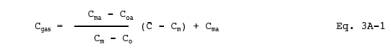
Where:
Cgas = Effluent gas
concentration, dry basis, percent.
Cma = Actual concentration
of the upscale calibration gas, percent.
Coa = Actual concentration
of the low-level calibration gas, percent.
Cm = Average of initial and
final system calibration bias check responses for the upscale calibration gas,
percent.
Co = Average of initial and
final system calibration bias check responses for the low level gas, percent.
¯C
= Average gas concentration indicated by the gas analyzer, dry basis, percent.
10.
BIBLIOGRAPHY
Same
as in Bibliography of Method 6C.