METHOD 15A -
DETERMINATION OF TOTAL REDUCED SULFUR EMISSIONS FROM SULFUR RECOVERY PLANTS IN
PETROLEUM REFINERIES
NOTE: This method does not include all of the
specifications (e.g.,
equipment and supplies) and procedures (e.g., sampling and analytical) essential to its
performance. Some material is incorporated by reference from other methods in
this part. Therefore, to obtain reliable results, persons using this method
should have a thorough knowledge of at least the following additional test
methods: Method 1, Method 6,
Method 15, and Method 16A.
6.1.3 Combustion Air
Delivery System.
6.1.7 Vacuum Gauge and
Rate Meter.
6.2 Sample Recovery and
Analysis.
7.2 Sample Recovery and
Analysis.
8.0 Sample Collection,
Preservation, Storage, and Transport.
8.1 Preparation of
Sampling Train.
10.0 Calibration and
Standardization.
12.0 Data Analysis and
Calculations.
12.2 Dry Sample Gas
Volume, Corrected to Standard Conditions.
12.3 Combustion Air Gas
Volume, corrected to Standard Conditions.
12.4 Concentration of
reduced sulfur compounds as ppm SO2.
12.5 Concentration of
Generated Recovery Gas.
12.6 Recovery
Efficiency for the System Performance Check.
14.0 Pollution
Prevention. [Reserved]
15.0 Waste Management.
[Reserved]
17.0 Tables, Diagrams,
Flowcharts, and Validation Data.
1.0 Scope and Application.
1.1 Analytes.
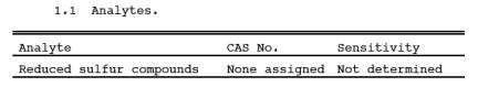
1.2 Applicability.
This method is
applicable for the determination of emissions of reduced sulfur compounds from
sulfur recovery plants where the emissions are in a reducing atmosphere, such
as in Stretford units.
1.3 Data Quality Objectives.
Adherence to the
requirements of this method will enhance the quality of the data obtained from
air pollutant sampling methods.
2.0 Summary of Method.
2.1 An integrated gas
sample is extracted from the stack, and combustion air is added to the oxygen
(O2)-deficient gas at a known rate. The reduced
sulfur compounds [including carbon disulfide (CS2),
carbonyl sulfide (COS), and hydrogen sulfide (H2S)]
are thermally oxidized to sulfur dioxide (SO2), which
is then collected in hydrogen peroxide as sulfate ion and analyzed according to
the Method 6 barium-thorin titration procedure.
3.0 Definitions. [Reserved]
4.0 Interferences.
4.1 Reduced sulfur
compounds, other than CS2, COS, and H2S, that
are present in the emissions will also be oxidized to SO2, causing a positive bias relative to emission standards that limit
only the three compounds listed above. For example, thiophene has been
identified in emissions from a Stretford unit and produced a positive bias of
30 percent in the Method 15A result. However, these biases may not affect the
outcome of the test at units where emissions are low relative to the standard.
4.2 Calcium and
aluminum have been shown to interfere in the Method 6 titration procedure.
Since these metals have been identified in particulate matter emissions from
Stretford units, a Teflon filter is required to minimize this interference.
4.3 Dilution of the
hydrogen peroxide (H2O2) absorbing solution
can potentially reduce collection efficiency, causing a negative bias. When
used to sample emissions containing 7 percent moisture or less, the midget
impingers have sufficient volume to contain the condensate collected during
sampling. Dilution of the H2O2 does not affect the collection of SO2. At
higher moisture contents, the potassium citrate-citric acid buffer system used
with Method 16A should be used to collect the condensate.
5.0 Safety.
5.1 Disclaimer.
This method may
involve hazardous materials, operations, and equipment. This test method may
not address all of the safety problems associated with its use. It is the
responsibility of the user of this test method to establish appropriate safety
and health practices and determine the applicability of regulatory limitations
prior to performing this test method.
5.2 Corrosive reagents.
The following
reagents are hazardous. Personal protective equipment and safe procedures are
useful in preventing chemical splashes. If contact occurs, immediately flush
with copious amounts of water for at least 15 minutes. Remove clothing under
shower and decontaminate. Treat residual chemical burns as thermal burns.
5.2.1 Hydrogen
Peroxide (H2O2). Irritating to eyes,
skin, nose, and lungs.
5.2.2 Sodium
Hydroxide (NaOH). Causes severe damage to eyes and skin. Inhalation causes
irritation to nose, throat, and lungs. Reacts exothermically with limited
amounts of water.
5.2.3 Sulfuric Acid
(H2SO4). Rapidly
destructive to body tissue. Will cause third degree burns. Eye damage may
result in blindness. Inhalation may be fatal from spasm of the larynx, usually
within 30 minutes. May cause lung tissue damage with edema. 3 mg/m3 will cause lung damage in uninitiated. 1 mg/m3 for 8 hours will cause lung damage or, in higher concentrations,
death. Provide ventilation to limit inhalation. Reacts violently with metals
and organics.
6.0 Equipment and Supplies.
6.1 Sample Collection.
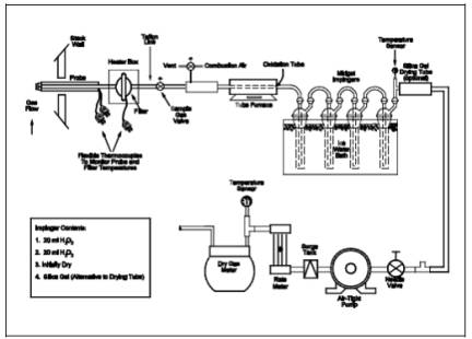
The sampling train
used in performing this method is shown in Figure 15A-1,
and component parts are discussed below. Modifications to this sampling train
are acceptable provided that the system performance check is met.
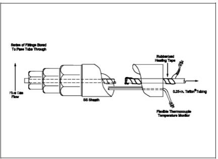
6.1.1 Probe.
6.4-mm (1/4-in.) OD
Teflon tubing sequentially wrapped with heat-resistant fiber strips, a
rubberized heating tape (with a plug at one end), and heat-resistant adhesive
tape. A flexible thermocouple or some other suitable temperature-measuring
device shall be placed between the Teflon tubing and the fiber strips so that
the temperature can be monitored. The probe should be sheathed in stainless
steel to provide in-stack rigidity. A series of bored-out stainless steel
fittings placed at the front of the sheath will prevent flue gas from entering
between the probe and sheath. The sampling probe is depicted in Figure 15A-2.
6.1.2 Particulate Filter.
A 50-mm Teflon filter
holder and a 1- to 2-mm porosity Teflon filter (available through Savillex
Corporation, 5325 Highway 101, Minnetonka, Minnesota 55345). The filter holder
must be maintained in a hot box at a temperature high enough to prevent
condensation.
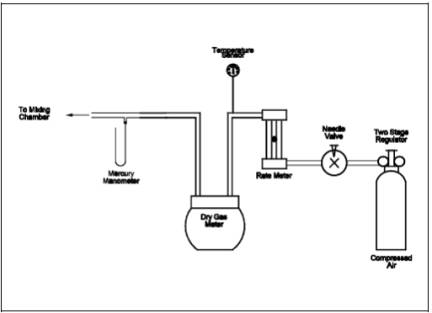
6.1.3 Combustion Air Delivery System.
As shown in the
schematic diagram in Figure 15A-3. The rate meter
should be selected to measure an air flow rate of 0.5 liter/min (0.02 ft3/min).
6.1.4 Combustion Tube.
Quartz glass tubing
with an expanded combustion chamber 2.54 cm (1 in.) in diameter and at least
30.5 cm (12 in.) long. The tube ends should have an outside diameter of 0.6 cm
(1/4 in.) and be at least 15.3 cm (6 in.) long. This length is necessary to
maintain the quartz-glass connector near ambient temperature and thereby avoid
leaks. Alternatively, the outlet may be constructed with a 90 degree glass
elbow and socket that would fit directly onto the inlet of the first peroxide
impinger.
6.1.5 Furnace.
Of sufficient size to
enclose the combustion tube. The furnace must have a temperature regulator
capable of maintaining the temperature at 1100 ±
50 ˚C (2,012 ± 90
˚F). The furnace operating temperature must be checked with a thermocouple to
ensure accuracy. Lindberg furnaces have been found to be satisfactory.
6.1.6 Peroxide Impingers, Stopcock Grease, Temperature Sensor, Drying Tube, Valve, Pump, and Barometer.
Same as in Method 6, Sections 6.1.1.2, 6.1.1.4, 6.1.1.5,
6.1.1.6, 6.1.1.7, 6.1.1.8, and 6.1.2, respectively, except that the midget
bubbler of Method 6, Section 6.1.1.2 is not required.
6.1.7 Vacuum Gauge and Rate Meter.
At least 760 mm Hg
(30 in. Hg) gauge and rotameter, or equivalent, capable of measuring flow rate
to ±5 percent of the selected flow rate and calibrated as in Section 10.2.
6.1.8 Volume Meter.
Dry gas meter capable
of measuring the sample volume under the particular sampling conditions with an
accuracy of 2 percent.
6.1.9 U-tube manometer.
To measure the
pressure at the exit of the combustion gas dry gas meter.
6.2 Sample Recovery and Analysis.
Same as Method 6, Sections 6.2 and 6.3, except a 10-ml
buret with 0.05-ml graduations is required for titrant volumes of less than
10.0 ml, and the spectrophotometer is not needed.
7.0 Reagents and Standards.
NOTE: Unless otherwise indicated, all reagents must
conform to the specifications established by the Committee on Analytical
Reagents of the American Chemical Society. When such specifications are not
available, the best available grade shall be used.
7.1 Sample Collection.
The following
reagents and standards are required for sample analysis:
7.1.1 Water. Same as Method 6, Section 7.1.1.
7.1.2 Hydrogen
Peroxide (H2O2), 3 Percent by
Volume. Same as Method 6, Section 7.1.3 (40 ml is needed per sample).
7.1.3 Recovery Check
Gas. Carbonyl sulfide in nitrogen [100 parts per million by volume (ppmv) or
greater, if necessary] in an aluminum cylinder. Concentration certified by the
manufacturer with an accuracy of ±2 percent or better, or verified by gas
chromatography where the instrument is calibrated with a COS permeation tube.
7.1.4 Combustion Gas.
Air, contained in a gas cylinder equipped with a two-stage regulator. The gas
shall contain less than 50 ppb of reduced sulfur compounds and less than 10 ppm
total hydrocarbons.
7.2 Sample Recovery and Analysis.
Same as Method 6, Sections 7.2 and 7.3.
8.0 Sample Collection, Preservation, Storage, and Transport.
8.1 Preparation of Sampling Train.
For the Method 6 part
of the train, measure 20 ml of 3 percent H2O2 into the first and second midget impingers. Leave the third midget
impinger empty and add silica gel to the fourth impinger. Alternatively, a
silica gel drying tube may be used in place of the fourth impinger. Place
crushed ice and water around all impingers. Maintain the oxidation furnace at
1100 ± 50 ˚C (2,012 ± 90 ˚F) to ensure 100 percent oxidation of COS. Maintain
the probe and filter temperatures at a high enough level (no visible
condensation) to prevent moisture condensation and monitor the temperatures
with a thermocouple.
8.2 Leak-Check Procedure.
Assemble the sampling
train and leak-check as described in Method 6,
Section 8.2. Include the combustion air delivery system from the needle
valve forward in the leak-check.
8.3 Sample Collection.
Adjust the pressure
on the second stage of the regulator on the combustion air cylinder to 10 psig.
Adjust the combustion air flow rate to 0.5 ± 0.05 L/min (1.1 ± 0.1 ft3/hr) before injecting combustion air into the sampling train. Then
inject combustion air into the sampling train, start the sample pump, and open
the stack sample gas valve. Carry out these three operations within 15 to 30 seconds
to avoid pressurizing the sampling train. Adjust the total sample flow rate to
2.0 ± 0.2 L/min (4.2 ± 0.4 ft3/hr). These flow rates
produce an O2 concentration of 5.0 percent in the stack gas,
which must be maintained constantly to allow oxidation of reduced sulfur
compounds to SO2. Adjust these flow rates during sampling as
necessary. Monitor and record the combustion air manometer reading at regular
intervals during the sampling period. Sample for 1 or 3 hours. At the end of
sampling, turn off the sample pump and combustion air simultaneously (within 30
seconds of each other). All other procedures are the same as in Method 6,
Section 8.3, except that the sampling train should not be purged. After
collecting the sample, remove the probe from the stack and conduct a leak-check
according to the procedures outlined in Section 8.2 of Method 6 (mandatory).
After each 3-hour test run (or after three 1-hour samples), conduct one system
performance check (see Section 8.5). After this system performance check and
before the next test run, it is recommended that the probe be rinsed and
brushed and the filter replaced.
NOTE: In Method 15, a test run is composed of 16
individual analyses (injects) performed over a period of not less than 3 hours
or more than 6 hours. For Method 15A to be consistent with Method 15, the
following may be used to obtain a test run: (1) collect three 60-minute samples
or (2) collect one 3-hour sample. (Three test runs constitute a test.)
8.4 Sample Recovery.
Recover the hydrogen
peroxide-containing impingers as detailed in Method
6, Section 8.4.
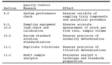
8.5 System Performance Check.
8.5.1 A system
performance check is done (1) to validate the sampling train components and
procedure (before testing, optional) and (2) to validate a test run (after a
run, mandatory). Perform a check in the field before testing consisting of at
least two samples (optional), and perform an additional check after each 3-hour
run or after three 1-hour samples (mandatory).
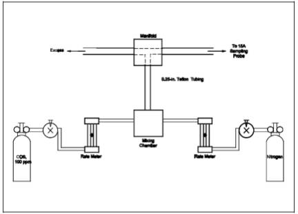
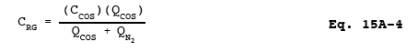
8.5.2 The checks
involve sampling a known concentration of COS and comparing the analyzed
concentration with the known concentration. Mix the recovery gas with N2 as shown in Figure 15A-4 if dilution is
required. Adjust the flow rates to generate a COS concentration in the range of
the stack gas or within 20 percent of the applicable standard at a total flow
rate of at least 2.5 L/min (5.3 ft3/hr). Use
Equation 15A-4 (see Section 12.5) to calculate the
concentration of recovery gas generated. Calibrate the flow rate from both
sources with a soap bubble flow tube so that the diluted concentration of COS
can be accurately calculated. Collect 30-minute samples, and analyze in the
same manner as the emission samples. Collect the samples through the probe of
the sampling train using a manifold or some other suitable device that will
ensure extraction of a representative sample.
8.5.3 The recovery
check must be performed in the field before replacing the particulate filter
and before cleaning the probe. A sample recovery of 100 ± 20 percent must be
obtained for the data to be valid and should be reported with the emission
data, but should not be used to correct the data. However, if the performance check
results do not affect the compliance or noncompliance status of the affected
facility, the Administrator may decide to accept the results of the compliance
test. Use Equation 15A-5 (see Section 12.6) to calculate the recovery
efficiency.
9.0 Quality Control.
10.0 Calibration and Standardization.
10.1 Metering System,
Temperature Sensors, Barometer, and Barium Perchlorate Solution. Same as Method 6, Sections 10.1, 10.2, 10.4, and 10.5,
respectively.
10.2
Rate Meter. Calibrate with a bubble flow tube.
11.0 Analytical Procedure.
11.1 Sample Loss
Check and Sample Analysis. Same as Method 6,
Sections 11.1 and 11.2.
11.2 Audit Sample
Analysis. Same as Method 6, Section 11.3.
12.0 Data Analysis and Calculations.
In the calculations,
retain at least one extra decimal figure beyond that of the acquired data.
Round off figures after final calculations.
12.1 Nomenclature.
CCOS = Concentration of COS recovery gas, ppm.
CRG(act) = Actual concentration of recovery check gas
(after dilution), ppm.
CRG(m) = Measured concentration of recovery check gas
generated, ppm.
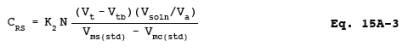
CRS = Concentration of reduced sulfur compounds as
SO2, dry basis, corrected to standard conditions, ppm.
N = Normality of
barium perchlorate titrant, milliequivalents/ml.
Pbar = Barometric pressure at exit orifice of the dry
gas meter, mm Hg.
Pstd = Standard absolute pressure, 760 mm Hg.
QCOS = Flow rate of COS recovery gas, liters/min.
QN = Flow rate of diluent N2,
liters/min.
R = Recovery
efficiency for the system performance check, percent.
Tm = Average dry gas meter absolute temperature,˚K.
Tstd = Standard absolute temperature, 293 ˚K.
Va = Volume of sample aliquot titrated, ml.
Vms = Dry gas volume as measured by the sample train
dry gas meter, liters.
Vmc = Dry gas volume as measured by the combustion
air dry gas meter, liters.
Vms(std) = Dry gas volume measured by the sample train
dry gas meter, corrected to standard conditions, liters.
Vmc(std) = Dry gas volume measured by the combustion air
dry gas meter, corrected to standard conditions, liters.
Vsoln = Total volume of solution in which the sulfur
dioxide sample is contained, 100 ml.
Vt = Volume of barium perchlorate titrant used for the sample (average
of replicate titrations), ml.
Vtb = Volume of barium perchlorate titrant used for
the blank, ml.
Y = Calibration
factor for sampling train dry gas meter.
Yc = Calibration factor for combustion air dry gas meter.
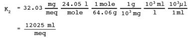
32.03 = Equivalent
weight of sulfur dioxide, mg/meq.
![]()
12.2 Dry Sample Gas Volume, Corrected to Standard Conditions.
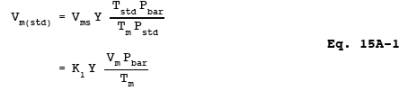
where:
K1 = 0.3855 ˚K/mm Hg for metric units,
= 17.65 ˚R/in. Hg for
English units.
12.3 Combustion Air Gas Volume, corrected to Standard Conditions.
![]()
NOTE: Correct Pbar for the
average pressure of the manometer during the sampling period.
12.4 Concentration of reduced sulfur compounds as ppm SO2.
where:
12.5 Concentration of Generated Recovery Gas.
12.6 Recovery Efficiency for the System Performance Check.
![]()
13.0 Method Performance.
13.1 Analytical Range.
The lower detectable
limit is 0.1 ppmv when sampling at 2 lpm for 3 hours or 0.3 ppmv when sampling
at 2 lpm for 1 hour. The upper concentration limit of the method exceeds
concentrations of reduced sulfur compounds generally encountered in sulfur
recovery plants.
13.2 Precision.
Relative standard
deviations of 2.8 and 6.9 percent have been obtained when sampling a stream
with a reduced sulfur compound concentration of 41 ppmv as SO2 for 1 and 3 hours, respectively.
13.3 Bias.
No analytical bias
has been identified. However, results obtained with this method are likely to
contain a positive bias relative to emission regulations due to the presence of
non-regulated sulfur compounds (that are present in petroleum) in the
emissions. The magnitude of this bias varies accordingly, and has not been
quantified.
14.0 Pollution Prevention. [Reserved]
15.0 Waste Management. [Reserved]
16.0 References.
1. American Society
for Testing and Materials Annual Book of ASTM Standards. Part 31: Water,
Atmospheric Analysis. Philadelphia, Pennsylvania. 1974. pp. 40-42.
2. Blosser, R.O., H.S.
Oglesby, and A.K. Jain. A Study of Alternate SO2 Scrubber
Designs Used for TRS Monitoring. National Council of the Paper Industry for Air
and Stream Improvement, Inc., New York, New York. Special Report 77-05. July
1977.
3. Curtis, F., and
G.D. McAlister. Development and Evaluation of an Oxidation/Method 6 TRS
Emission Sampling Procedure. Emission Measurement Branch, Emission Standards
and Engineering Division, U.S. Environmental Protection Agency, Research
Triangle Park, North Carolina. February 1980.
4. Gellman, I. A
Laboratory and Field Study of Reduced Sulfur Sampling and Monitoring Systems.
National Council of the Paper Industry for Air and Stream Improvement, Inc.,
New York, New York. Atmospheric Quality Improvement Technical Bulletin No. 81.
October 1975.
5. Margeson, J.H., et
al. A Manual Method for TRS
Determination. Journal of Air Pollution Control Association. 35:1280-1286.
December 1985.
17.0 Tables, Diagrams, Flowcharts, and Validation Data.
Figure
15A-1. Method 15A Sampling Train.
Figure
15A-2. Method 15A Sampling Probe.
Figure
15A-3. Combustion Air Delivery System.
Figure
15A-4. Recovery Gas Generator System.