Method
2H-Determination of Stack Gas Velocity Taking Into Account Velocity Decay Near
the Stack Wall
3.1 Complete wall
effects traverse
3.4 ‘‘May,’’ ‘‘Must,’’
‘‘Shall,’’ ‘‘Should,’’ and the imperative form of verbs.
3.4.2 ‘‘Must,’’
‘‘Shall,’’ and the imperative form of verbs
(such as ‘‘record’’ or ‘‘enter’’)
3.6 Method 1 exterior
equal-area sector and Method 1 equal-area sector closest to the wall
3.7 Method 1 interior
equal-area sector
3.8 Method 1 traverse
point and Method 1 equal-area traverse point
3.12 1-in. incremented
wall effects traverse point
3.13 Partial wall
effects traverse
3.14 Relative accuracy
test audit (RATA)
3.15 Wall
effects-unadjusted average velocity
3.16 Wall
effects-adjusted average velocity
3.17 Wall effects
traverse point
7.0 Reagents and
Standards. [Reserved]
8.0 Sample Collection
and Analysis
8.1 Default Wall
Effects Adjustment Factors.
8.2.1 Method 1
equal-area traverse point locations.
8.2.2 Partial wall
effects traverse.
8.2.3 Complete wall
effects traverse.
8.3 Traverse Point
Sampling Order and Probe Selection.
8.4 Measurements at
Method 1 and Wall Effects Traverse Points.
8.4.1 Probe residence
time at wall effects traverse points.
8.4.2 Temperature
measurement for wall effects traverse points.
8.4.3 Non-detectable
velocity pressure at wall effects traverse points.
8.6 Point Velocity
Calculation.
8.7 Tabulating Calculated
Point Velocity Values for Wall Effects Traverse Points.
8.7.1 Point velocity
values at wall effects traverse points other than dlast.
8.7.2 Point velocity
value at dlast.
8.7.3 Point velocity
value (vdrem) at drem.
9.1 Particulate Matter
Build-up in Horizontal Ducts.
9.2 Verifying Traverse
Point Distances.
9.2.2 Automated probe
systems.
12.0 Data Analysis and
Calculations
13.0 Method
Performance. [Reserved]
14.0 Pollution
Prevention. [Reserved]
15.0 Waste Management.
[Reserved]
16.1.1 Description of
the source and site.
16.1.4 Quality
assurance and control.
16.2 Reporting a
Default Wall Effects Adjustment Factor.
1.0 Scope and Application
1.1 This
method is applicable in conjunction with Methods 2,
2F, and 2G (40 CFR
Part 60, Appendix A) to account for velocity decay near the wall in circular
stacks and ducts.
1.2 This
method is not applicable for testing stacks and ducts less than 3.3 ft (1.0 m)
in diameter.
1.3 Data Quality
Objectives. Adherence to the requirements of this method will enhance the
quality of the data obtained from air pollutant sampling methods.
2.0 Summary of Method
2.1 A wall
effects adjustment factor is determined. It is used to adjust the average stack
gas velocity obtained under Method 2, 2F, or 2G of this appendix to take into
account velocity decay near the stack or duct wall.
2.2 The method
contains two possible procedures: a calculational approach which derives an
adjustment factor from velocity measurements and a default procedure which
assigns a generic adjustment factor based on the construction of the stack or
duct.
2.2.1 The
calculational procedure derives a wall effects adjustment factor from velocity
measurements taken using Method 2, 2F, or 2G at 16 (or more) traverse points
specified under Method 1 of this appendix and a total of eight (or more) wall
effects traverse points specified under this method. The calculational
procedure based on velocity measurements is not applicable for horizontal
circular ducts where build-up of particulate matter or other material in the
bottom of the duct is present.
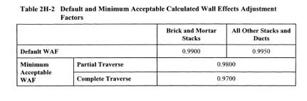
2.2.2 A
default wall effects adjustment factor of 0.9900 for brick and mortar stacks
and 0.9950 for all other types of stacks and ducts may be used without taking
wall effects measurements in a stack or duct.
2.3 When the
calculational procedure is conducted as part of a relative accuracy test audit
(RATA) or other multiple-run test procedure, the wall effects adjustment factor
derived from a single traverse (i.e., single RATA run) may be applied to all
runs of the same RATA without repeating the wall effects measurements.
Alternatively, wall effects adjustment factors may be derived for several
traverses and an average wall effects adjustment factor applied to all runs of
the same RATA.
3.0 Definitions.
3.1 Complete wall effects traverse
A traverse in
which measurements are taken at drem (see section 3.3) and at 1-in. intervals in each of the four
Method 1 equal-area sectors closest to the wall,
beginning not farther than 4 in. (10.2 cm) from the wall and extending either
(1) across the entire width of the Method 1 equal-area sector or (2) for stacks
or ducts where this width exceeds 12 in. (30.5 cm) (i.e., stacks or ducts
greater than or equal to 15.6 ft [4.8 m] in diameter), to a distance of not
less than 12 in. (30.5 cm) from the wall. Note: Because this method specifies
that measurements must be taken at whole number multiples of 1 in. from a stack
or duct wall, for clarity numerical quantities in this method are expressed in
English units followed by metric units in parentheses. To enhance readability,
hyphenated terms such as ‘‘1-in. intervals’’ or ‘‘1-in. incremented,’’ are
expressed in English units only.
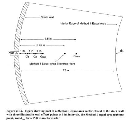
3.2 dlast.
Depending on
context, dlast means
either (1) the distance from the wall of the last 1-in. incremented wall
effects traverse point or (2) the traverse point located at that distance (see Figure 2H-2).
3.3 drem.
Depending on
context, drem means
either (1) the distance from the wall of the centroid of the area between dlast
and the interior edge of
the Method 1 equal-area sector closest to the wall or (2) the traverse point
located at that distance (see Figure 2H-2).
3.4 ‘‘May,’’ ‘‘Must,’’ ‘‘Shall,’’ ‘‘Should,’’ and the imperative form of
verbs.
3.4.1 ‘‘May’’
Used to
indicate that a provision of this method is optional.
3.4.2 ‘‘Must,’’ ‘‘Shall,’’ and the imperative form of verbs (such as ‘‘record’’ or ‘‘enter’’)
Used to
indicate that a provision of this method is mandatory.
3.4.3 ‘‘Should’’
Used to
indicate that a provision of this method is not mandatory but is highly
recommended as good practice.
3.5 Method 1
Refers to 40
CFR part 60, appendix A, ‘‘Method 1 - Sample and velocity traverses for
stationary sources.’’
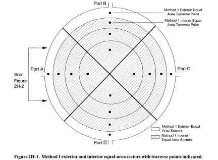
3.6 Method 1 exterior equal-area sector and Method 1 equal-area sector closest to the wall
Any one of the
four equal-area sectors that are closest to the wall for a circular stack or
duct laid out in accordance with section 2.3.1 of Method 1 (see Figure 2H-1).
3.7 Method 1 interior equal-area sector
Any of the
equal-area sectors other than the Method 1 exterior equal-area sectors (as
defined in section 3.6) for a circular stack or duct laid out in accordance
with section 2.3.1 of Method 1 (see Figure 2H-1).
3.8 Method 1 traverse point and Method 1 equal-area traverse point
A traverse
point located at the centroid of an equal-area sector of a circular stack laid
out in accordance with section 2.3.1 of Method 1.
3.9 Method 2
Refers to 40
CFR part 60, appendix A, ‘‘Method 2 - Determination of stack gas velocity and
volumetric flow rate (Type S pitot tube).’’
3.10 Method 2F
Refers to 40
CFR part 60, appendix A, ‘‘Method 2F - Determination of stack gas velocity and
volumetric flow rate with three-dimensional probes.’’
3.11 Method 2G
Refers to 40
CFR part 60, appendix A, ‘‘Method 2G - Determination of stack gas velocity and
volumetric flow rate with two-dimensional probes.’’
3.12 1-in. incremented wall effects traverse point
Any of the
wall effects traverse points that are located at 1-in. intervals, i.e.,
traverse points d1 through dlast (see
Figure 2H-2).
3.13 Partial wall effects traverse
A traverse in
which measurements are taken at fewer than the number of traverse points
required for a ‘‘complete wall effects traverse’’ (as defined in section 3.1),
but are taken at a minimum of two traverse points in each Method 1 equal-area
sector closest to the wall, as specified in section 8.2.2.
3.14 Relative accuracy test audit (RATA)
A field test
procedure performed in a stack or duct in which a series of concurrent
measurements of the same stack gas stream is taken by a reference method and an
installed monitoring system. A RATA usually consists of series of 9 to 12 sets
of such concurrent measurements, each of which is referred to as a RATA run. In
a volumetric flow RATA, each reference method run consists of a complete
traverse of the stack or duct.
3.15 Wall effects-unadjusted average velocity
The average
stack gas velocity, not accounting for velocity decay near the wall, as
determined in accordance with Method 2, 2F, or 2G for a Method 1 traverse
consisting of 16 or more points.
3.16 Wall effects-adjusted average velocity
The average
stack gas velocity, taking into account velocity decay near the wall, as
calculated from measurements at 16 or more Method 1 traverse points and at the
additional wall effects traverse points specified in this method.
3.17 Wall effects traverse point
A traverse
point located in accordance with sections 8.2.2 or 8.2.3 of this method.
4.0 Interferences. [Reserved]
5.0 Safety
5.1 This method
may involve hazardous materials, operations, and equipment. This method does
not purport to address all of the health and safety considerations associated
with its use. It is the responsibility of the user of this method to establish
appropriate health and safety practices and to determine the applicability of
occupational health and safety regulatory requirements prior to performing this
method.
6.0 Equipment and Supplies
6.1 The
provisions pertaining to equipment and supplies in the method that is used to
take the traverse point measurements (i.e., Method 2, 2F, or 2G) are applicable
under this method.
7.0 Reagents and Standards. [Reserved]
8.0 Sample Collection and Analysis
8.1 Default Wall Effects Adjustment Factors.
A default wall
effects adjustment factor of 0.9900 for brick and mortar stacks and 0.9950 for
all other types of stacks and ducts may be used without conducting the
following procedures.
8.2 Traverse Point Locations.
Determine the
location of the Method 1 traverse points in accordance with section 8.2.1 and
the location of the traverse points for either a partial wall effects traverse
in accordance with section 8.2.2 or a complete wall effects traverse in
accordance with section 8.2.3.
8.2.1 Method 1 equal-area traverse point locations.
Determine the
location of the Method 1 equal-area traverse points for a traverse consisting
of 16 or more points using Table 1-2 (Location of Traverse Points in Circular
Stacks) of Method 1.
8.2.2 Partial wall effects traverse.
For a partial
wall effects traverse, measurements must be taken at a minimum of the following
two wall effects traverse point locations in all four Method 1 equal-area
sectors closest to the wall: (1) 1 in. (2.5 cm) from the wall (except as
provided in section 8.2.2.1) and (2) drem, as determined using Equation 2H-1 or 2H-2 (see section
8.2.2.2).
8.2.2.1 If the
probe cannot be positioned at 1 in. (2.5 cm) from the wall (e.g., because of
insufficient room to withdraw the probe shaft) or if velocity pressure cannot
be detected at 1 in. (2.5 cm) from the wall (for any reason other than build-up
of particulate matter in the bottom of a duct), take measurements at the 1-in.
incremented wall effects traverse point closest to the wall where the probe can
be positioned and velocity pressure can be detected.
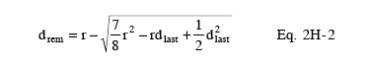
8.2.2.2
Calculate the distance of drem
from the wall to within ±1⁄4 in. (6.4 mm) using Equation 2H-1 or Equation 2H-2
(for a 16-point traverse).
![]()
Where:
r = the stack or duct radius determined from
direct measurement of the stack or duct diameter in accordance with section 8.6
of Method 2F or Method 2G, in. (cm);
p = the number of Method 1 equal-area
traverse points on a diameter, p 3
8 (e.g., for a 16-point traverse, p = 8); For a
16-point Method 1 traverse, Equation 2H-1 becomes:
8.2.2.3
Measurements may be taken at any number of additional wall effects traverse
points, with the following provisions.
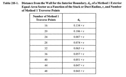
(a) dlast must not be closer to the center of the
stack or duct than the distance of the interior edge (boundary), db, of the Method 1 equal-area sector
closest to the wall (see Figure 2H-2 or 2H-3). That is,
Where:
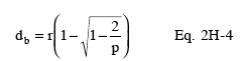
Table 2H-1
shows db as a
function of the stack or duct radius, r, for traverses ranging from 16 to 48 points (i.e., for
values of p ranging
from 8 to 24).
(b) Each point
must be located at a distance that is a whole number (e.g., 1, 2, 3) multiple
of 1 in. (2.5 cm).
(c) Points do
not have to be located at consecutive 1-in. intervals. That is, one or more
1-in. incremented points may be skipped. For example, it would be acceptable
for points to be located at 1 in. (2.5 cm), 3 in. (7.6 cm), 5 in. (12.7 cm), dlast, and drem; or at 1 in. (2.5 cm), 2 in. (5.1 cm), 4
in. (10.2 cm), 7 in. (17.8 cm), dlast, and drem.
Follow the instructions in section 8.7.1.2 of this method for recording results
for wall effects traverse points that are skipped. It should be noted that the
full extent of velocity decay may not be accounted for if measurements are not
taken at all 1-in. incremented points close to the wall.
8.2.3 Complete wall effects traverse.
For a complete
wall effects traverse, measurements must be taken at the following points in
all four Method 1 equal-area sectors closest to the wall.
(a) The 1-in. incremented
wall effects traverse point closest to the wall where the probe can be
positioned and velocity can be detected, but no farther than 4 in. (10.2 cm)
from the wall.
(b) Every
subsequent 1-in. incremented wall effects traverse point out to the interior
edge of the Method 1 equal-area sector or to 12 in. (30.5 cm) from the wall,
whichever comes first. Note: In stacks or ducts with diameters greater than
15.6 ft (4.8 m) the interior edge of the Method 1 equal-area sector is farther
from the wall than 12 in. (30.5 cm).
(c) drem, as determined using Equation 2H-1 or
2H-2 (as applicable). Note: For a complete traverse of a stack or duct with a
diameter less than 16.5 ft (5.0 m), the distance between drem and dlast is less than or equal to 1⁄2 in.
(12.7 mm). As discussed in section 8.2.4.2, when the distance between drem and dlast is less than or equal to 1⁄2 in.
(12.7 mm), the velocity measured at dlast may be used for drem. Thus, it is not necessary to calculate the distance of drem or to take measurements at drem when conducting a complete traverse
of a stack or duct with a diameter less than 16.5 ft (5.0 m).
8.2.4 Special considerations.
The following
special considerations apply when the distance between traverse points is less
than or equal to 1⁄2 in. (12.7 mm).
8.2.4.1 A wall
effects traverse point and the Method 1 traverse point. If the distance between
a wall effects traverse point and the Method 1 traverse point is less than or
equal to 1⁄2 in. (12.7 mm), taking measurements at both points is allowed but
not required or recommended; if measurements are taken at only one point, take
the measurements at the point that is farther from the wall and use the
velocity obtained at that point as the value for both points (see sections
8.2.3 and 9.2 for related requirements).
8.2.4.2 drem and dlast. If the distance between drem and dlast is less than or equal to 1⁄2 in.
(12.7 mm), taking measurements at drem
is allowed but not required or recommended; if measurements are not taken at drem, the measured velocity value at dlast must be used as the value for both dlast and drem.
8.3 Traverse Point Sampling Order and Probe Selection.
Determine the
sampling order of the Method 1 and wall effects traverse points and select the
appropriate probe for the measurements, taking into account the following
considerations.
8.3.1 Traverse
points on any radius may be sampled in either direction (i.e., from the wall
toward the center of the stack or duct, or vice versa).
8.3.2 To
reduce the likelihood of velocity variations during the time of the traverse
and the attendant potential impact on the wall effects-adjusted and unadjusted
average velocities, the following provisions of this method shall be met.
8.3.2.1 Each complete
set of Method 1 and wall effects traverse points accessed from the same port
shall be sampled without interruption. Unless traverses are performed
simultaneously in all ports using separate probes at each port, this provision
disallows first sampling all Method 1 points at all ports and then sampling all
the wall effects points.
8.3.2.2 The
entire integrated Method 1 and wall effects traverse across all test ports
shall be as short as practicable, consistent with the measurement system
response time (see section 8.4.1.1) and sampling (see section 8.4.1.2)
provisions of this method.
8.3.3 It is
recommended but not required that in each Method 1 equal-area sector closest to
the wall, the Method 1 equal-area traverse point should be sampled in sequence
between the adjacent wall effects traverse points. For example, for the
traverse point configuration shown in Figure 2H-2, it is recommended that the
Method 1 equal-area traverse point be sampled between dlast and drem. In this example, if the traverse is
conducted from the wall toward the center of the stack or duct, it is
recommended that measurements be taken at points in the following order: d1, d2, dlast,
the Method 1 traverse point, drem,
and then at the traverse points in the three Method 1 interior equal area
sectors.
8.3.4 The same
type of probe must be used to take measurements at all Method 1 and wall
effects traverse points. However, different copies of the same type of probe
may be used at different ports (e.g., Type S probe 1 at port A, Type S probe 2
at port B) or at different traverse points accessed from a particular port
(e.g., Type S probe 1 for Method 1 interior traverse points accessed from port
A, Type S probe 2 for wall effects traverse points and the Method 1 exterior
traverse point accessed from port A). The identification number of the probe
used to obtain measurements at each traverse point must be recorded.
8.4 Measurements at Method 1 and Wall Effects Traverse Points.
Conduct
measurements at Method 1 and wall effects traverse points in accordance with
Method 2, 2F, or 2G and in accordance with the provisions of the following
subsections (some of which are included in Methods 2F and 2G but not in Method
2), which are particularly important for wall effects testing.
8.4.1 Probe residence time at wall effects traverse points.
Due to the
steep temperature and pressure gradients that can occur close to the wall, it
is very important for the probe residence time (i.e., the total time spent at a
traverse point) to be long enough to ensure collection of representative
temperature and pressure measurements. The provisions of Methods 2F and 2G in
the following subsections shall be observed.
8.4.1.1 System
response time. Determine the response time of each probe measurement system by
inserting and positioning the ‘‘cold’’ probe (at ambient temperature and
pressure) at any Method 1 traverse point. Read and record the probe
differential pressure, temperature, and elapsed time at 15-second intervals
until stable readings for both pressure and temperature are achieved. The
response time is the longer of these two elapsed times. Record the response
time.
8.4.1.2
Sampling. At the start of testing in each port (i.e., after a probe has been
inserted into the stack gas stream), allow at least the response time to elapse
before beginning to take measurements at the first traverse point accessed from
that port. Provided that the probe is not removed from the stack gas stream,
measurements may be taken at subsequent traverse points accessed from the same
test port without waiting again for the response time to elapse.
8.4.2 Temperature measurement for wall effects traverse points.
Either (1)
take temperature measurements at each wall effects traverse point in accordance
with the applicable provisions of Method 2, 2F, or 2G; or (2) use the
temperature measurement at the Method 1 traverse point closest to the wall as
the temperature measurement for all the wall effects traverse points in the
corresponding equal-area sector.
8.4.3 Non-detectable velocity pressure at wall effects traverse points.
If the probe
cannot be positioned at a wall effects traverse point or if no velocity
pressure can be detected at a wall effects point, measurements shall be taken
at the first subsequent wall effects traverse point farther from the wall where
velocity can be detected. Follow the instructions in section 8.7.1.2 of this
method for recording results for wall effects traverse points where velocity
pressure cannot be detected. It should be noted that the full extent of
velocity decay may not be accounted for if measurements are not taken at the
1-in. incremented wall effects traverse points closest to the wall.
8.5 Data Recording.
For each wall
effects and Method 1 traverse point where measurements are taken, record all
pressure, temperature, and attendant measurements prescribed in section 3 of
Method 2 or section 8.0 of Method 2F or 2G, as applicable.
8.6 Point Velocity Calculation.
For each wall
effects and Method 1 traverse point, calculate the point velocity value (vi) in accordance with sections 12.1 and
12.2 of Method 2F for tests using Method 2F and in accordance with sections
12.1 and 12.2 of Method 2G for tests using Method 2 and Method 2G. (Note that
the term (vi) in this
method corresponds to the term (va(i)) in Methods 2F and 2G.) When the
equations in the indicated sections of Method 2G are used in deriving point
velocity values for Method 2 tests, set the value of the yaw angles appearing
in the equations to 0°.
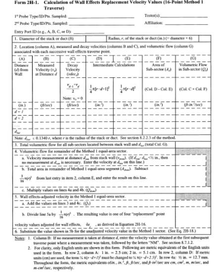
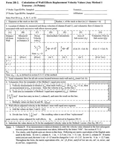
8.7 Tabulating Calculated Point Velocity Values for Wall Effects Traverse Points.
Enter the
following values in a hardcopy or electronic form similar to Form
2H-1 (for 16-point Method 1 traverses) or Form 2H-2
(for Method 1 traverses consisting of more than 16 points). A separate form
must be completed for each of the four Method 1 equal-area sectors that are
closest to the wall.
(a) Port ID
(e.g., A, B, C, or D)
(b) Probe type
(c) Probe ID
(d) Stack or
duct diameter in ft (m) (determined in accordance with section 8.6 of Method 2F
or Method 2G)
(e) Stack or
duct radius in in. (cm)
(f) Distance
from the wall of wall effects traverse points at 1-in. intervals, in ascending
order starting with 1 in. (2.5 cm) (column A of Form 2H-1 or 2H-2)
(g) Point
velocity values (vd)
for 1-in. incremented traverse points (see section 8.7.1), including dlast (see section 8.7.2)
(h) Point
velocity value (vdrem)
at drem (see section
8.7.3).
8.7.1 Point velocity values at wall effects traverse points other than dlast.
For every
1-in. incremented wall effects traverse point other than dlast, enter in column B of Form 2H-1 or 2H-2
either the velocity measured at the point (see section 8.7.1.1) or the velocity
measured at the first subsequent traverse point farther from the wall (see
section 8.7.1.2). A velocity value must be entered in column B of Form 2H-1 or
2H-2 for every 1-in. incremented traverse point from d1 (representing the wall effects traverse
point 1 in. [2.5 cm] from the wall) to dlast.
8.7.1.1 For
wall effects traverse points where the probe can be positioned and velocity
pressure can be detected, enter the value obtained in accordance with section
8.6.
8.7.1.2 For
wall effects traverse points that were skipped [see section 8.2.2.3(c)] and for
points where the probe cannot be positioned or where no velocity pressure can
be detected, enter the value obtained at the first subsequent traverse point
farther from the wall where velocity pressure was detected and measured and
follow the entered value with a ‘‘flag,’’ such as the notation ‘‘NM,’’ to
indicate that ‘‘no measurements’’ were actually taken at this point.
8.7.2 Point velocity value at dlast.
For dlast, enter in column B of Form 2H-1 or 2H-2
the measured value obtained in accordance with section 8.6.
8.7.3 Point velocity value (vdrem) at drem.
Enter the
point velocity value obtained at drem in column G of row 4a in Form 2H-1 or 2H-2. If the distance
between drem and dlast
is less than or equal to
1⁄2 in. (12.7 mm), the measured velocity value at dlast may be used as the value at drem (see section 8.2.4.2).
9.0 Quality Control.
9.1 Particulate Matter Build-up in Horizontal Ducts.
Wall effects
testing of horizontal circular ducts should be conducted only if build-up of
particulate matter or other material in the bottom of the duct is not present.
9.2 Verifying Traverse Point Distances.
In taking
measurements at wall effects traverse points, it is very important for the
probe impact pressure port to be positioned as close as practicable to the
traverse point locations in the gas stream. For this reason, before beginning
wall effects testing, it is important to calculate and record the traverse
point positions that will be marked on each probe for each port, taking into
account the distance that each port nipple (or probe mounting flange for
automated probes) extends out of the stack and any extension of the port nipple
(or mounting flange) into the gas stream. To ensure that traverse point
positions are properly identified, the following procedures should be performed
on each probe used.
9.2.1 Manual probes.
Mark the probe
insertion distance of the wall effects and Method 1 traverse points on the
probe sheath so that when a mark is aligned with the outside face of the stack
port, the probe impact port is located at the calculated distance of the
traverse point from the stack inside wall. The use of different colored marks
is recommended for designating the wall effects and Method 1 traverse points.
Before the first use of each probe, check to ensure that the distance of each
mark from the center of the probe impact pressure port agrees with the
previously calculated traverse point positions to within ±1⁄4 in. (6.4 mm).
9.2.2 Automated probe systems.
For automated
probe systems that mechanically position the probe head at prescribed traverse
point positions, activate the system with the probe assemblies removed from the
test ports and sequentially extend the probes to the programmed location of
each wall effects traverse point and the Method 1 traverse points. Measure the
distance between the center of the probe impact pressure port and the inside of
the probe assembly mounting flange for each traverse point. The measured
distances must agree with the previously calculated traverse point positions to
within ±1⁄4 in. (6.4 mm).
9.3 Probe Installation.
Properly
sealing the port area is particularly important in taking measurements at wall
effects traverse points. For testing involving manual probes, the area between
the probe sheath and the port should be sealed with a tightly fitting flexible
seal made of an appropriate material such as heavy cloth so that leakage is
minimized. For automated probe systems, the probe assembly mounting flange area
should be checked to verify that there is no leakage.
9.4 Velocity Stability.
This method
should be performed only when the average gas velocity in the stack or duct is
relatively constant over the duration of the test. If the average gas velocity
changes significantly during the course of a wall effects test, the test
results should be discarded.
10.0 Calibration
10.1 The
calibration coefficient(s) or curves obtained under Method 2, 2F, or 2G and
used to perform the Method 1 traverse are applicable under this method.
11.0 Analytical Procedure
11.1 Sample
collection and analysis are concurrent for this method (see section 8).
12.0 Data Analysis and Calculations
12.1 The
following calculations shall be performed to obtain a wall effects adjustment
factor (WAF) from (1)
the wall effects unadjusted average velocity (vavg), (2) the replacement velocity (vˆej) for each of the four Method 1 sectors
closest to the wall, and (3) the average stack gas velocity that accounts for velocity
decay near the wall (vˆ avg).
12.2
Nomenclature. The following terms are listed in the order in which they appear
in Equations 2H-5 through 2H-21.
vavg=the average stack gas velocity,
unadjusted for wall effects, actual ft/sec(m/sec);
vii=stack gas point velocity value at Method
1 interior equal-area sectors, actual ft/sec (m/sec);
vej=stack gas point velocity value,
unadjusted for wall effects, at Method 1 exterior equal area sectors, actual
ft/sec (m/sec);
i=index of Method 1 interior equal-area
traverse points;
j=index of Method 1 exterior equal-area
traverse points;
n=total number of traverse points in the
Method 1 traverse;
vdecd=the wall effects decay velocity for a
sub-sector located between the traverse points at distances d- 1 (in metric units, d- 2.5)
and d from the wall,
actual ft/sec (m/sec);
vd=the measured stack gas velocity at
distance d from the
wall, actual ft/sec (m/sec); Note: v0=0;
d=the distance of a 1-in. incremented wall
effects traverse point from the wall, for traverse points d1 through dlast, in. (cm);
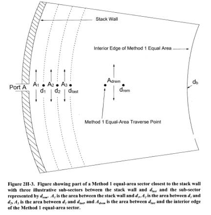
Ad=the cross-sectional area of a sub-sector
located between the traverse points at distances d- 1 (in metric units, d- 2.5)
and d from the wall,
in.2 (cm 2) ( e.g., sub-sector A2 shown in Figures 2H-3
and 2H-4);
r=the stack or duct radius, in. (cm);
Qd=the stack gas volumetric flow rate for a
sub-sector located between the traverse points at distances d- 1 (in metric units, d- 2.5)
and d from the wall,
actual ft-in.2/sec (m-cm 2/sec);
![]() dlast =the total stack gas volumetric flow rate
for all sub-sectors located between the wall and dlast, actual ft-in.2/sec (m-cm 2/sec);
dlast=the distance
from the wall of the last 1-in. incremented wall effects traverse point, in.
(cm);
dlast =the total stack gas volumetric flow rate
for all sub-sectors located between the wall and dlast, actual ft-in.2/sec (m-cm 2/sec);
dlast=the distance
from the wall of the last 1-in. incremented wall effects traverse point, in.
(cm);
Adrem=the cross-sectional area of the
sub-sector located between dlast and
the interior edge of the Method 1 equal-area sector closest to the wall, in.2
(cm 2) (see Figure 2H-4);
p=the number of Method 1 traverse points
per diameter, p ≥8
(e.g., for a 16-point traverse, p=8);
drem=the distance from the wall of the
centroid of the area between dlast and
the interior edge of the Method 1 equal-area sector closest to the wall, in.
(cm);
Qdrem=the total stack gas volumetric flow rate
for the sub-sector located between dlast and the interior edge of the Method 1 equal area sector
closest to the wall, actual ftin. 2/sec (m-cm 2/sec);
vdrem=the measured stack gas velocity at
distance drem from
the wall, actual ft/sec (m/sec);
QT=the total stack gas volumetric flow rate
for the Method 1 equal-area sector closest to the wall, actual ft-in.2/sec
(m-cm 2/sec);
vˆ ej=the replacement stack gas velocity for
the Method 1 equal-area sector closest to the wall, i.e., the stack gas point
velocity value, adjusted for wall effects, for the jth Method
1 equal-area
sector closest to the wall, actual ft/sec (m/sec);
vˆ avg=the average stack gas velocity that
accounts for velocity decay near the wall, actual ft/sec (m/sec);
WAF=the wall effects adjustment factor
derived from vavg and
vˆ avg for a single
traverse, dimensionless;
vˆ final=the final wall effects-adjusted average
stack gas velocity that replaces the unadjusted average stack gas velocity
obtained using Method 2, 2F, or 2G for a field test consisting of a single
traverse, actual ft/sec (m/sec);
WAF=the wall effects adjustment factor that
is applied to the average velocity, unadjusted for wall effects, in order to
obtain the final wall effects-adjusted stack gas velocity, vˆ final or, vˆ final(k), dimensionless;
vˆ final(k)=the final wall effects-adjusted average stack gas velocity
that replaces the unadjusted average stack gas velocity obtained using Method
2, 2F, or 2G on run k of
a RATA or other multiple-run field test procedure, actual ft/sec (m/sec);
vˆ avg(k)=the average stack gas velocity, obtained on run k of a RATA or other multiple-run
procedure, unadjusted for velocity decay near the wall, actual ft/sec (m/sec);
k=index of runs in a RATA or other
multiple-run procedure.
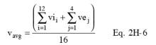
12.3 Calculate
the average stack gas velocity that does not account for velocity decay near
the wall (vavg) using
Equation 2H-5.
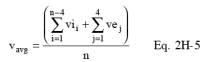
(Note that vavg in Equation 2H-5 is the same as v(a)avg in
Equations 2F-9 and 2G-8 in Methods 2F and 2G, respectively.) For a 16-point traverse,
Equation 2H-5 may be written as follows:
12.4 Calculate
the replacement velocity, vˆ ej,
for each of the four Method 1 equal-area sectors closest to the wall using the
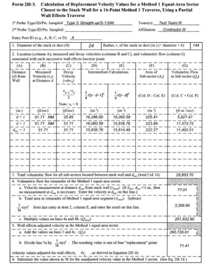
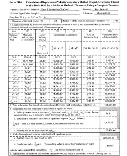
procedures described in sections 12.4.1 through 12.4.8. Forms 2H-1 and 2H-2 provide
sample tables that may be used in either hardcopy or spreadsheet format to
perform the calculations described in sections 12.4.1 through 12.4.8. Forms 2H-3 and 2H-4 provide examples of
Form 2H-1 filled in for partial and complete wall effects traverses.
12.4.1
Calculate the average velocity (designated the ‘‘decay velocity,’’ vdecd) for
each sub-sector located between the wall and dlast (see Figure 2H-3) using Equation
2H-7.
![]()
For each line
in column A of Form 2H-1 or 2H-2 that contains a value of d, enter the
corresponding calculated value of vdecd in column C.
12.4.2
Calculate the cross-sectional area between the wall and the first 1-in.
incremented wall effects traverse point and between successive 1-in.
incremented wall effects traverse points, from the wall to dlast (see Figure 2H-3),
using Equation 2H-8.
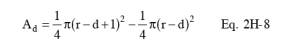
For each line
in column A of Form 2H-1 or 2H-2 that contains a value of d, enter the value of
the expression 1⁄4 π(r-
d+1)2 in
column D, the value of the expression 1⁄4 π(r- d)2 in column E, and the value of Ad in column F. Note that Equation 2H-8 is
designed for use only with English units (in.). If metric units (cm) are used,
the first term, 1⁄4 π(r-
d+1)2,
must be changed to 1⁄4 π(r-
d+2.5)2.
This change must also be made in column D of Form 2H-1 or 2H-2.
12.4.3
Calculate the volumetric flow through each cross-sectional area derived in
section 12.4.2 by multiplying the values of vdecd, derived according to section 12.4.1, by
the cross-sectional areas derived in section 12.4.2 using Equation 2H-9.
![]()
For each line
in column A of Form 2H-1 or 2H-2 that contains a value of d, enter the
corresponding calculated value of Qd in
column G.
12.4.4
Calculate the total volumetric flow through all sub-sectors located between the
wall and dlast, using
Equation 2H-10.
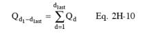
Enter the
calculated value of Qd1 Õdlast in line 3 of column G of Form 2H-1 or
2H-2.
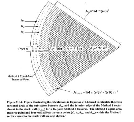
12.4.5
Calculate the cross-sectional area of the sub-sector located between dlast and the interior edge of the Method 1
equal-area sector (e.g., sub-sector Adrem shown in Figures 2H-3 and 2H-4) using Equation 2H-11.
![]()
For a 16-point
traverse (eight points per diameter), Equation 2H-11 may be written as follows:
![]()
Enter the
calculated value of Adrem
in line 4b of column G of Form 2H-1 or 2H-2.
12.4.6
Calculate the volumetric flow for the sub-sector located between dlast and the interior edge of the Method
1 equal-area sector, using Equation 2H-13.
![]()
In Equation
2H-13, µdrem is either (1) the measured velocity value at drem or (2) the measured velocity at dlast, if the distance between ddrem and dlast is less than or equal to 1⁄2 in.
(12.7 mm) and no velocity measurement is taken at drem (see section 8.2.4.2). Enter the
calculated value of Qdrem
in line 4c of column G of Form 2H-1 or 2H-2.
12.4.7
Calculate the total volumetric flow for the Method 1 equal-area sector closest
to the wall, using Equation 2H-14.
![]()
Enter the
calculated value of QT
in line 5a of column G of Form 2H-1 or 2H-2.
12.4.8
Calculate the wall effects-adjusted replacement velocity value for the Method 1
equal-area sector closest to the wall, using Equation 2H-15.
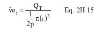
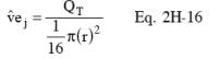
For a 16-point
traverse (eight points per diameter), Equation 2H-15 may be written as follows:
Enter the
calculated value of vˆej in
line 5b of column G of Form 2H-1 or 2H-2.
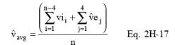
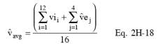
12.5 Calculate
the wall effects-adjusted average velocity,, by replacing the four values of õ avg shown in Equation 2H-5 with the four
wall effects-adjusted replacement velocity values, Ã µe, calculated according to section 12.4.8, using Equation
2H-17.
For a 16-point
traverse, Equation 2H-17 may be written as follows:
12.6 Calculate
the wall effects adjustment factor, WAF, using Equation 2H-19.
![]()
12.6.1 Partial
wall effects traverse. If a partial wall effects traverse (see section 8.2.2)
is conducted, the value obtained from Equation 2H-19 is acceptable and may be
reported as the wall effects adjustment factor provided that the value is
greater than or equal to 0.9800. If the value is less than 0.9800, it shall not
be used and a wall effects adjustment factor of 0.9800 may be used instead.
12.6.2
Complete wall effects traverse. If a complete wall effects traverse (see
section 8.2.3) is conducted, the value obtained from Equation 2H-19 is
acceptable and may be reported as the wall effects adjustment factor provided
that the value is greater than or equal to 0.9700. If the value is less than
0.9700, it shall not be used and a wall effects adjustment factor of 0.9700 may
be used instead. If the wall effects adjustment factor for a particular stack
or duct is less than 0.9700, the tester may (1) repeat the wall effects test,
taking measurements at more Method 1 traverse points and (2) recalculate the
wall effects adjustment factor from these measurements, in an attempt to obtain
a wall effects adjustment factor that meets the 0.9700 specification and
completely characterizes the wall effects.
12.7 Applying
a Wall Effects Adjustment Factor. A default wall effects adjustment factor, as
specified in section 8.1, or a calculated wall effects adjustment factor
meeting the requirements of section 12.6.1 or 12.6.2 may be used to adjust the
average stack gas velocity obtained using Methods 2, 2F, or 2G to take into
account velocity decay near the wall of circular stacks or ducts. Default wall
effects adjustment factors specified in section 8.1 and calculated wall effects
adjustment factors that meet the requirements of section 12.6.1 and 12.6.2 are
summarized in Table 2H-2.
12.7.1
Single-run tests. Calculate the final wall effects-adjusted average stack gas
velocity for field tests consisting of a single traverse using Equation 2H-20.
![]()
The wall effects
adjustment factor, WAF, shown in Equation 2H-20, may be (1) a default wall
effects adjustment factor, as specified in section 8.1, or (2) a calculated
adjustment factor that meets the specifications in sections 12.6.1 or 12.6.2.
If a calculated adjustment factor is used in Equation 2H-20, the factor must
have been obtained during the same traverse in which µavg was obtained.
12.7.2 RATA or
other multiple run test procedure. Calculate the final wall effects adjusted
average stack gas velocity for any run k of a RATA or other multiple-run procedure using Equation
2H–21.
![]()
The wall
effects adjustment factor, WAF, shown in Equation 2H-21 may be (1) a default
wall effects adjustment factor, as specified in section 8.1; (2) a calculated adjustment
factor (meeting the specifications in sections 12.6.1 or 12.6.2) obtained from
any single run of the RATA that includes run k; or (3) the arithmetic average of more
than one WAF (each meeting the specifications in sections 12.6.1 or 12.6.2)
obtained through wall effects testing conducted during several runs of the RATA
that includes run k.
If wall effects adjustment factors (meeting the specifications in sections
12.6.1 or 12.6.2) are determined for more than one RATA run, the arithmetic
average of all of the resulting calculated wall effects adjustment factors must
be used as the value of WAF and
applied to all runs of that RATA. If a calculated, not a default, wall effects
adjustment factor is used in Equation 2H-21, the average velocity unadjusted
for wall effects, µavg(k), must be obtained from runs in which the number of
Method 1 traverse points sampled does not exceed the number of Method 1
traverse points in the runs used to derive the wall effects adjustment factor,
WAF, shown in Equation 2H-21.
12.8
Calculating Volumetric Flow Using Final Wall Effects-Adjusted Average Velocity
Value. To obtain a stack gas flow rate that accounts for velocity decay near
the wall of circular stacks or ducts, replace µs in Equation 2-10 in Method 2, or µa(avg) a in Equations 2F-10 and 2F-11 in Method 2F, or µa(avg) in Equations 2G-9 and 2G-10 in Method 2G with one of the
following.
12.8.1 For
single-run test procedures, use the final wall effects-adjusted average stack
gas velocity, µfinal, calculated
according to Equation 2H-20.
12.8.2 For
RATA and other multiple run test procedures, use the final wall effects
adjusted average stack gas velocity, µfinal(k), calculated
according to Equation 2H-21.
13.0 Method Performance. [Reserved]
14.0 Pollution Prevention. [Reserved]
15.0 Waste Management. [Reserved]
16.0 Reporting
16.1 Field Test Reports.
Field test
reports shall be submitted to the Agency according to the applicable regulatory
requirements. When Method 2H is performed in conjunction with Method 2, 2F, or
2G to derive a wall effects adjustment factor, a single consolidated Method
2H/2F (or 2H/2G) field test report should be prepared. At a minimum, the
consolidated field test report should contain (1) all of the general
information, and data for Method 1 points, specified in section 16.0 of Method
2F (when Method 2H is used in conjunction with Method 2F) or section 16.0 of
Method 2G (when Method 2H is used in conjunction with Method 2 or 2G) and (2)
the additional general information, and data for Method 1 points and wall
effects points, specified in this section (some of which are included in
section 16.0 of Methods 2F and 2G and are repeated in this section to ensure
complete reporting for wall effects testing).
16.1.1 Description of the source and site.
The field test
report should include the descriptive information specified in section 16.1.1
of Method 2F (when using Method 2F) or 2G (when using either Method 2 or 2G).
It should also include a description of the stack or duct’s construction
material along with the diagram showing the dimensions of the stack or duct at
the test port elevation prescribed in Methods 2F and 2G. The diagram should
indicate the location of all wall effects traverse points where measurements
were taken as well as the Method 1 traverse points. The diagram should provide
a unique identification number for each wall effects and Method 1 traverse
point, its distance from the wall, and its location relative to the probe entry
ports.
16.1.2 Field test forms.
The field test
report should include a copy of Form 2H-1, 2H-2, or an equivalent for each
Method 1 exterior equal-area sector.
16.1.3 Field test data.
The field test
report should include the following data for the Method 1 and wall effects
traverse.
16.1.3.1 Data
for each traverse point. The field test report should include the values
specified in section 16.1.3.2 of Method 2F (when using Method 2F) or 2G (when
using either Method 2 or 2G) for each Method 1 and wall effects traverse point.
The provisions of section 8.4.2 of Method 2H apply to the temperature
measurements reported for wall effects traverse points. For each wall effects
and Method 1 traverse point, the following values should also be included in
the field test report.
(a) Traverse
point identification number for each Method 1 and wall effects traverse point.
(b) Probe
type.
(c) Probe
identification number.
(d) Probe
velocity calibration coefficient (i.e., Cp when Method 2 or 2G is used; F2 when Method 2F is used). For each Method
1 traverse point in an exterior equal-area sector, the following additional
value should be included.
(e) Calculated
replacement velocity, vˆej,
accounting for wall effects.
16.1.3.2 Data
for each run. The values specified in section 16.1.3.3 of Method 2F (when using
Method 2F) or 2G (when using either Method 2 or 2G) should be included in the
field test report once for each run. The provisions of section 12.8 of Method
2H apply for calculating the reported gas volumetric flow rate. In addition,
the following Method 2H run values should also be included in the field test
report.
(a) Average
velocity for run, accounting for wall effects, vˆ avg.
(b) Wall
effects adjustment factor derived from a test run, WAF.
16.1.3.3 Data for
a complete set of runs. The values specified in section 16.1.3.4 of Method 2F
(when using Method 2F) or 2G (when using either Method 2 or 2G) should be
included in the field test report once for each complete set of runs. In
addition, the field test report should include the wall effects adjustment
factor, WAF, that is
applied in accordance with section 12.7.1 or 12.7.2 to obtain the final wall
effects-adjusted average stack gas velocity vˆ final or vˆ final(k).
16.1.4 Quality assurance and control.
Quality
assurance and control procedures, specifically tailored to wall effects
testing, should be described.
16.2 Reporting a Default Wall Effects Adjustment Factor.
When a default
wall effects adjustment factor is used in accordance with section 8.1 of this
method, its value and a description of the stack or duct’s construction
material should be reported in lieu of submitting a test report.
17.0 References.
(1) 40 CFR
Part 60, Appendix A, Method 1’Sample and velocity traverses for stationary
sources.
(2) 40 CFR
Part 60, Appendix A, Method 2’Determination of stack gas velocity and
volumetric flow rate (Type S pitot tube).
(3) 40 CFR
Part 60, Appendix A, Method 2F’Determination of stack gas velocity and
volumetric flow rate with three-dimensional probes.
(4) 40 CFR
Part 60, Appendix A, Method 2G’Determination of stack gas velocity and
volumetric flow rate with two-dimensional probes.
(5) 40 CFR
Part 60, Appendix A, Method 3’Gas analysis for carbon dioxide, oxygen, excess
air, and dry molecular weight.
(6) 40 CFR
Part 60, Appendix A, Method 3A - Determination of oxygen and carbon dioxide
concentrations in emissions from stationary sources (instrumental analyzer
procedure).
(7) 40 CFR
Part 60, Appendix A, Method 4 - Determination of moisture content in stack
gases.
(8) Emission
Measurement Center (EMC) Approved Alternative Method (ALT-011) ‘‘Alternative
Method 2 Thermocouple Calibration Procedure.’’
(9) The Cadmus
Group, Inc., 1998, ‘‘EPA Flow Reference Method Testing and Analysis: Data Report,
Texas Utilities, DeCordova Steam Electric Station, Volume I: Test Description
and Appendix A (Data Distribution Package),’’ EPA/430-R-98-015a.
(10) The
Cadmus Group, Inc., 1998, ‘‘EPA Flow Reference Method Testing and Analysis:
Data Report, Texas Utilities, Lake Hubbard Steam Electric Station, Volume I:
Test Description and Appendix A (Data Distribution Package),’’
EPA/430-R-98-017a.
(11) The
Cadmus Group, Inc., 1998, ‘‘EPA Flow Reference Method Testing and Analysis:
Data Report, Pennsylvania Electric Co., G.P.U. Genco Homer City Station: Unit
1, Volume I: Test Description and Appendix A (Data Distribution Package),’’
EPA/430-R-98-018a.
(12) The
Cadmus Group, Inc., May 1999, ‘‘EPA Flow Reference Method Testing and Analysis:
Findings Report,’’ EPA/430-R-99-009.
(13) The
Cadmus Group, Inc., 1997, ‘‘EPA Flow Reference Method Testing and Analysis:
Wind Tunnel Experimental Results,’’ EPA/430-R-97-013.
(14) National
Institute of Standards and Technology, 1998, ‘‘Report of Special Test of Air
Speed Instrumentation, Four Prandtl Probes, Four S-Type Probes, Four French
Probes, Four Modified Kiel Probes,’’ Prepared for the U.S. Environmental
Protection Agency under IAG No. DW13938432-01-0.
(15) National
Institute of Standards and Technology, 1998, ‘‘Report of Special Test of Air
Speed Instrumentation, Five Autoprobes,’’ Prepared for the U.S. Environmental
Protection Agency under IAG No. DW13938432-01-0.
(16) National
Institute of Standards and Technology, 1998, ‘‘Report of Special Test of Air
Speed Instrumentation, Eight Spherical Probes,’’ Prepared for the U.S.
Environmental Protection Agency under IAG No. DW13938432-01-0.
(17) National
Institute of Standards and Technology, 1998, ‘‘Report of Special Test of Air
Speed Instrumentation, Four DAT Probes,’’ Prepared for the U.S. Environmental
Protection Agency under IAG No. DW13938432-01-0.
(18)
Massachusetts Institute of Technology (MIT), 1998, ‘‘Calibration of Eight Wind
Speed Probes Over a Reynolds Number Range of 46,000 to 725,000 per Foot, Text
and Summary Plots,’’ Plus Appendices, WBWT-TR-1317, Prepared for The Cadmus
Group, Inc., under EPA Contract 68-W6-0050, Work Assignment 0007AA-3.
(19) Fossil
Energy Research Corporation, Final Report, ‘‘Velocity Probe Tests in Nonaxial
Flow Fields,’’ November 1998, Prepared for the U.S. Environmental Protection
Agency.
(20) Fossil
Energy Research Corporation, ‘‘Additional Swirl Tunnel Tests: E-DAT
and T-DAT
Probes,’’ February 24, 1999, Technical Memorandum Prepared for U.S.
Environmental Protection Agency, P.O. No. 7W-1193-NALX.