METHOD
13B - DETERMINATION OF TOTAL FLUORIDE EMISSIONS FROM STATIONARY SOURCES
(SPECIFIC ION ELECTRODE METHOD)
NOTE: This method does not include all of the
specifications (e.g.,
equipment and supplies) and procedures (e.g., sampling and analytical) essential to its
performance. Some material is incorporated by reference from other methods in
this part. Therefore, to obtain reliable results, persons using this method
should have a thorough knowledge of at least the following additional test
methods: Method 1, Method 2,
Method 3, Method 5, and
Method 13A.
6.1 Sample Collection
and Sample Recovery.
6.2 Sample Preparation
and Analysis.
7.1 Sample Collection
and Sample Recovery.
7.2 Sample Preparation
and Analysis.
8.0 Sample Collection,
Preservation, Storage, and Transport.
10.0 Calibration and
Standardizations.
11.1 Sample Loss Check,
Sample Preparation, and Distillation.
12.0 Data Analysis and
Calculations.
14.0 Pollution
Prevention. [Reserved]
15.0 Waste Management.
[Reserved]
18.0 Tables, Diagrams, Flowcharts, and Validation Data [Reserved]
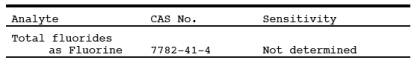
1.0 Scope and Application.
1.1 Analytes.
1.2 Applicability.
This method is
applicable for the determination of fluoride (F-)
emissions from sources as specified in the regulations. It does not measure
fluorocarbons, such as Freons.
1.3 Data Quality Objectives.
Adherence to the
requirements of this method will enhance the quality of the data obtained from
air pollutant sampling methods.
2.0 Summary.
Gaseous and
particulate F- are withdrawn isokinetically from the source and
collected in water and on a filter. The total F- is
then determined by the specific ion electrode method.
3.0 Definitions. [Reserved]
4.0 Interferences.
Grease on
sample-exposed surfaces may cause low F-results because of adsorption.
5.0 Safety.
5.1 Disclaimer.
This method may
involve hazardous materials, operations, and equipment. This test method does
not purport to address all of the safety problems associated with its use. It
is the responsibility of the user of this test method to establish appropriate
safety and health practices and to determine the applicability of regulatory
limitations prior to performing this test method.
5.2 Corrosive Reagents.
The following
reagents are hazardous. Personal protective equipment and safe procedures are
useful in preventing chemical splashes. If contact occurs, immediately flush
with copious amounts of water at least 15 minutes. Remove clothing under shower
and decontaminate. Treat residual chemical burn as thermal burn.
5.2.1 Sodium
Hydroxide (NaOH). Causes severe damage to eye tissues and to skin. Inhalation
causes irritation to nose, throat, and lungs. Reacts exothermically with
limited amounts of water.
5.2.2 Sulfuric Acid
(H2SO4). Rapidly
destructive to body tissue. Will cause third degree burns. Eye damage may
result in blindness. Inhalation may be fatal from spasm of the larynx, usually
within 30 minutes. May cause lung tissue damage with edema. 1 mg/m3 for 8 hours will cause lung damage or, in higher concentrations,
death. Provide ventilation to limit inhalation. Reacts violently with metals
and organics.
6.0 Equipment and Supplies.
6.1 Sample Collection and Sample Recovery.
Same as Method 13A, Sections 6.1 and 6.2,
respectively.
6.2 Sample Preparation and Analysis.
The following items
are required for sample preparation and analysis:
6.2.1 Distillation
Apparatus, Bunsen Burner, Electric Muffle Furnace, Crucibles, Beakers,
Volumetric Flasks, Erlenmeyer Flasks or Plastic Bottles, Constant Temperature
Bath, and Balance. Same as Method 13A,
Sections 6.3.1 to 6.3.9, respectively.
6.2.2 Fluoride Ion
Activity Sensing Electrode.
6.2.3 Reference
Electrode.
Single junction,
sleeve type.
6.2.4 Electrometer. A
pH meter with millivolt-scale capable of ± 0.1-mv resolution, or a specific ion
meter made specifically for specific ion electrode use.
6.2.5 Magnetic
Stirrer and Tetrafluoroethylene (TFE) Fluorocarbon-Coated Stirring Bars.
6.2.6 Beakers.
Polyethylene, 100-ml.
7.0 Reagents and Standards.
Unless otherwise
indicated, all reagents are to conform to the specifications established by the
Committee on Analytical Reagents of the American Chemical Society, where such
specifications are available. Otherwise, use the best available grade.
7.1 Sample Collection and Sample Recovery.
Same as Method 13A, Sections 7.1 and 7.2,
respectively.
7.2 Sample Preparation and Analysis.
The following
reagents and standards are required for sample analysis:
7.2.1 Calcium Oxide
(CaO). Certified grade containing 0.005 percent F- or
less.
7.2.2 Phenolphthalein
Indicator. Dissolve 0.1 g phenolphthalein in a mixture of 50 ml of 90 percent
ethanol and 50 ml water.
7.2.3 Sodium
Hydroxide (NaOH), Pellets.
7.2.4 Sulfuric Acid
(H2SO4),
Concentrated.
7.2.5 Filters.
Whatman No. 541, or equivalent.
7.2.6 Water. Same as
Section 7.1.2 of Method 13A.
7.2.7 Sodium
Hydroxide, 5 M. Dissolve 20 g of NaOH in 100 ml of water.
7.2.8 Sulfuric Acid,
25 Percent (v/v). Mix 1 part of concentrated H2SO4 with 3 parts of water.
7.2.9 Total Ionic
Strength Adjustment Buffer (TISAB). Place approximately 500 ml of water in a
1-liter beaker. Add 57 ml of glacial acetic acid, 58 g of sodium chloride, and
4 g of cyclohexylene dinitrilo tetraacetic acid. Stir to dissolve. Place the
beaker in a water bath and cool to 20 ˚C (68 ˚F). Slowly add 5 M NaOH to the
solution, measuring the pH continuously with a calibrated pH/reference
electrode pair, until the pH is 5.3. Pour into a 1-liter volumetric flask, and
dilute to volume with deionized, distilled water. Commercially prepared TISAB
may be substituted for the above.
7.2.10 Fluoride
Standard Solution, 0.1 M. Oven dry approximately 10 g of sodium fluoride (NaF)
for a minimum of 2 hours at 110 ˚C (230 ˚F), and store in a desiccator. Then
add 4.2 g of NaF to a 1-liter volumetric flask, and add enough water to
dissolve. Dilute to volume with water.
8.0 Sample Collection, Preservation, Storage, and Transport.
Same as Method 13A, Section 8.0.
9.0 Quality Control.
9.1 Miscellaneous
Quality Control Measures.
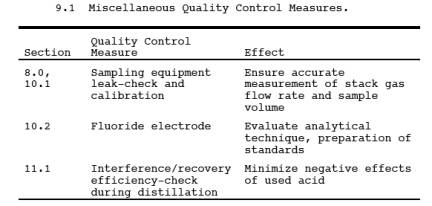
9.2 Volume Metering
System Checks. Same as Method 5, Section 9.2.
10.0 Calibration and Standardizations.
NOTE: Maintain a laboratory log of all calibrations.
10.1 Sampling Equipment.
Same as Method 13A, Section 10.1.
10.2 Fluoride Electrode.
Prepare fluoride
standardizing solutions by serial dilution of the 0.1 M fluoride standard
solution. Pipet 10 ml of 0.1 M fluoride standard solution into a 100-ml
volumetric flask, and make up to the mark with water for a 10-2 M standard solution. Use 10 ml of 10-2 M solution to make a 10-3 M solution in the same manner. Repeat the
dilution procedure, and make 10-4 and 10-5 M solutions.
10.2.1 Pipet 50 ml of
each standard into a separate beaker. Add 50 ml of TISAB to each beaker. Place the
electrode in the most dilute standard solution. When a steady millivolt reading
is obtained, plot the value on the linear axis of semi-log graph paper versus
concentration on the log axis. Plot the nominal value for concentration of the
standard on the log axis, (e.g.,
when 50 ml of 10-2 M standard is diluted with 50 ml of TISAB, the
concentration is still designated "10-2 M").
10.2.2 Between
measurements, soak the fluoride sensing electrode in water for 30 seconds, and
then remove and blot dry. Analyze the standards going from dilute to
concentrated standards. A straight-line calibration curve will be obtained,
with nominal concentrations of 10-4, 10-3, 10-2, 10-1 fluoride
molarity on the log axis plotted versus electrode potential (in mv) on the
linear scale. Some electrodes may be slightly nonlinear between 10-5 and 10-4 M. If
this occurs, use additional standards between these two concentrations.
10.2.3 Calibrate the
fluoride electrode daily, and check it hourly. Prepare fresh fluoride
standardizing solutions daily (10-2 M or
less). Store fluoride standardizing solutions in polyethylene or polypropylene
containers.
NOTE: Certain specific ion meters have been designed
specifically for fluoride electrode use and give a direct readout of fluoride
ion concentration. These meters may be used in lieu of calibration curves for
fluoride measurements over a narrow concentration ranges. Calibrate the meter
according to the manufacturer's instructions.
11.0 Analytical Procedures.
11.1 Sample Loss Check, Sample Preparation, and Distillation.
Same as Method 13A, Sections 11.1 through 11.3, except
that the NOTE following
Section 11.3.1 is not applicable.
11.2 Analysis.
11.2.1 Containers No.
1 and No. 2. Distill suitable aliquots from Containers No. 1 and No. 2. Dilute
the distillate in the volumetric flasks to exactly 250 ml with water, and mix
thoroughly. Pipet a 25-ml aliquot from each of the distillate into separate
beakers. Add an equal volume of TISAB, and mix. The sample should be at the
same temperature as the calibration standards when measurements are made. If
ambient laboratory temperature fluctuates more than ± 2 ˚C from the temperature
at which the calibration standards were measured, condition samples and standards
in a constant-temperature bath before measurement. Stir the sample with a
magnetic stirrer during measurement to minimize electrode response time. If the
stirrer generates enough heat to change solution temperature, place a piece of
temperature insulating material, such as cork, between the stirrer and the
beaker. Hold dilute samples (below 10-4 M
fluoride ion content) in polyethylene beakers during measurement.
11.2.2 Insert the
fluoride and reference electrodes into the solution. When a steady millivolt
reading is obtained, record it. This may take several minutes. Determine
concentration from the calibration curve. Between electrode measurements, rinse
the electrode with water.
11.2.3 Container No.
3 (Silica Gel). Same as in Method 13A,
Section 11.4.2.
12.0 Data Analysis and Calculations.
Carry out
calculations, retaining at least one extra significant figure beyond that of
the acquired data. Round off figures after final calculation.
12.1 Nomenclature.
Same as Method 13A, Section 12.1, with the
addition of the following:
M = F- concentration from calibration curve, molarity.
12.2 Average DGM
Temperature and Average Orifice Pressure Drop, Dry Gas Volume, Volume of Water
Vapor and Moisture Content, Fluoride Concentration in Stack Gas, and Isokinetic
Variation. Same as Method 13A, Sections 12.2 to 12.4, 12.6, and 12.7,
respectively.
12.3 Total Fluoride
in Sample. Calculate the amount of F- in the
sample using Equation 13B-1:
![]()
where:
K = 19
[(mg·l)/(mole·ml)] (metric units)
= 0.292 [(gr·l)/(mole·ml)]
(English units)
13.0 Method Performance.
The following
estimates are based on a collaborative test done at a primary aluminum smelter.
In the test, six laboratories each sampled the stack simultaneously using two
sampling trains for a total of 12 samples per sampling run. Fluoride
concentrations encountered during the test ranged from 0.1 to 1.4 mg F-/m3.
13.1 Precision. The
intra-laboratory and inter-laboratory standard deviations, which include
sampling and analysis errors, are 0.037 mg F-/m3 with 60 degrees of freedom and 0.056 mg F-/m3 with five degrees of freedom, respectively.
13.2 Bias. The collaborative
test did not find any bias in the analytical method.
13.3 Range. The range
of this method is 0.02 to 2,000 µg F-/ml;
however, measurements of less than 0.1 µg F- /ml
require extra care.
14.0 Pollution Prevention. [Reserved]
15.0 Waste Management. [Reserved]
16.0 Alternative Procedures.
16.1 Compliance with
ASTM D 3270-73T, 91, 95 "Analysis for Fluoride Content of the Atmosphere
and Plant Tissues (Semi-automated Method)" is an acceptable alternative
for the distillation and analysis requirements specified in Sections 11.1 and
11.2 when applied to suitable aliquots of Containers 1 and 2 samples.
17.0 References.
Same as Method 13A, Section 16.0, References 1 and 2,
with the following addition:
1. MacLeod, Kathryn
E., and Howard L. Crist. Comparison of the SPADNS- Zirconium Lake and Specific
Ion Electrode Methods of Fluoride Determination in Stack Emission Samples.
Analytical Chemistry. 45:1272-1273. 1973.
18.0 Tables,
Diagrams, Flowcharts, and Validation Data. [Reserved]