METHOD
13A - DETERMINATION OF TOTAL FLUORIDE EMISSIONS FROM STATIONARY SOURCES (SPADNS
ZIRCONIUM LAKE METHOD)
NOTE: This method does not include all of the
specifications (e.g.,
equipment and supplies) and procedures (e.g., sampling and analytical) essential to its
performance. Some material is incorporated by reference from other methods in
this part. Therefore, to obtain reliable results, persons using this method
should have a thorough knowledge of at least the following additional test
methods: Method 1, Method 2, Method 3, and Method 5.
5.2.1 Hydrochloric Acid
(HCl). Highly toxic.
5.2.2 Sodium Hydroxide
(NaOH).
6.3 Sample Preparation
and Analysis.
7.3 Sample Preparation
and Analysis.
8.0 Sample Collection,
Preservation, Storage, and Transport.
8.2 Preliminary
Determinations.
8.3 Preparation of
Sampling Train.
10.0 Calibration and
Standardization.
12.0 Data Analysis and
Calculations.
14.0 Pollution
Prevention. [Reserved]
15.0 Waste Management.
[Reserved]
18.0 Tables, Diagrams,
Flowcharts, and Validation Data.
1.0 Scope and Application.
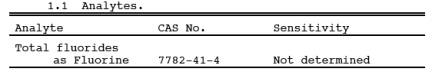
1.1 Analytes.
1.2 Applicability.
This method is
applicable for the determination of fluoride (F-)
emissions from sources as specified in the regulations. It does not measure
fluorocarbons, such as Freons.
1.3 Data Quality Objectives.
Adherence to the
requirements of this method will enhance the quality of the data obtained from
air pollutant sampling methods.
2.0 Summary.
Gaseous and
particulate F- are withdrawn isokinetically from the source and
collected in water and on a filter. The total F- is then
determined by the SPADNS Zirconium Lake Colorimetric method.
3.0 Definitions. [Reserved]
4.0 Interferences.
4.1 Chloride.
Large quantities of
chloride will interfere with the analysis, but this interference can be
prevented by adding silver sulfate into the distillation flask (see Section 11.3). If chloride ion is present, it may be
easier to use the specific ion electrode method of analysis (Method 13B).
4.2 Grease.
Grease on sample-exposed
surfaces may cause low F-
results due to adsorption.
5.0 Safety.
5.1 Disclaimer.
This method may
involve hazardous materials, operations, and equipment. This test method may
not address all of the safety problems associated with its use. It is the
responsibility of the user of this test method to establish appropriate safety
and health practices and to determine the applicability of regulatory
limitations prior to performing this test method.
5.2 Corrosive Reagents.
The following
reagents are hazardous. Personal protective equipment and safe procedures are
useful in preventing chemical splashes. If contact occurs, immediately flush
with copious amounts of water at least 15 minutes. Remove clothing under shower
and decontaminate. Treat residual chemical burn as thermal burn.
5.2.1 Hydrochloric Acid (HCl). Highly toxic.
Vapors are highly
irritating to eyes, skin, nose, and lungs, causing severe damage. May cause
bronchitis, pneumonia, or edema of lungs. Exposure to concentrations of 0.13 to
0.2 percent can be lethal in minutes. Will react with metals, producing
hydrogen.
5.2.2 Sodium Hydroxide (NaOH).
Causes severe damage
to eye tissues and to skin. Inhalation causes irritation to nose, throat, and
lungs. Reacts exothermically with limited amounts of water.
5.2.3 Sulfuric Acid (H2SO4).
Rapidly destructive
to body tissue. Will cause third degree burns. Eye damage may result in
blindness. Inhalation may be fatal from spasm of the larynx, usually within 30
minutes. May cause lung tissue damage with edema. 1 mg/m3 for 8 hours will cause lung damage or, in higher concentrations,
death. Provide ventilation to limit inhalation. Reacts violently with metals
and organics.
6.0 Equipment and Supplies.
6.1 Sample Collection.
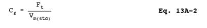
A schematic of the
sampling train used in performing this method is shown in Figure
13A-1; it is similar to the Method 5 sampling train except that the filter
position is interchangeable. The sampling train consists of the following
components:
6.1.1 Probe Nozzle, Pitot Tube, Differential Pressure Gauge, Filter Heating System, Temperature Sensor, Metering System, Barometer, and Gas Density Determination Equipment.
Same as Method 5, Sections 6.1.1.1, 6.1.1.3 through
6.1.1.7, 6.1.1.9, 6.1.2, and 6.1.3, respectively. The filter heating system and
temperature sensor are needed only when moisture condensation is a problem.
6.1.2 Probe Liner.
Borosilicate glass or
316 stainless steel. When the filter is located immediately after the probe, a
probe heating system may be used to prevent filter plugging resulting from
moisture condensation, but the temperature in the probe shall not be allowed to
exceed 120 ± 14 ˚C (248 ± 25 ˚F).
6.1.3 Filter Holder.
With positive seal
against leakage from the outside or around the filter. If the filter is located
between the probe and first impinger, use borosilicate glass or stainless steel
with a 20-mesh stainless steel screen filter support and a silicone rubber
gasket; do not use a glass frit or a sintered metal filter support. If the
filter is located between the third and fourth impingers, borosilicate glass
with a glass frit filter support and a silicone rubber gasket may be used.
Other materials of construction may be used, subject to the approval of the
Administrator.
6.1.4 Impingers.
Four impingers
connected as shown in Figure 13A-1 with ground-glass (or equivalent),
vacuum-tight fittings. For the first, third, and fourth impingers, use the
Greenburg-Smith design, modified by replacing the tip with a 1.3-cm (1/2-in.)
ID glass tube extending to 1.3 cm (1/2 in.) from the bottom of the flask. For
the second impinger, use a Greenburg-Smith impinger with the standard tip.
Modifications (e.g.,
flexible connections between the impingers or materials other than glass) may
be used, subject to the approval of the Administrator. Place a temperature
sensor, capable of measuring temperature to within 1 ˚C (2 ˚F), at the outlet
of the fourth impinger for monitoring purposes.
6.2 Sample Recovery.
The following items
are needed for sample recovery:
6.2.1 Probe-liner and
Probe-Nozzle Brushes, Wash Bottles, Graduated Cylinder and/or Balance, Plastic
Storage Containers, Funnel and Rubber Policeman, and Funnel. Same as Method 5, Sections 6.2.1, 6.2.2 and 6.2.5 to
6.2.8, respectively.
6.2.2 Sample Storage
Container. Wide-mouth, high-density polyethylene bottles for impinger water
samples, 1 liter.
6.3 Sample Preparation and Analysis.
The following items
are needed for sample preparation and analysis:
6.3.1
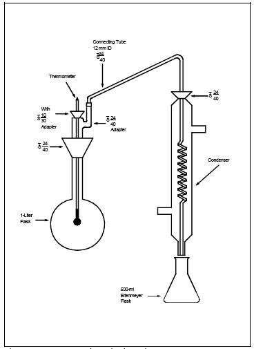
Distillation Apparatus. Glass distillation apparatus assembled as shown in Figure 13A-2.
6.3.2 Bunsen Burner.
6.3.3 Electric Muffle
Furnace. Capable of heating to 600 ˚C (1100 ˚F).
6.3.4 Crucibles.
Nickel, 75- to 100-ml.
6.3.5 Beakers. 500-ml
and 1500-ml.
6.3.6 Volumetric
Flasks. 50-ml.
6.3.7 Erlenmeyer
Flasks or Plastic Bottles. 500-ml.
6.3.8 Constant Temperature
Bath. Capable of maintaining a constant temperature of ±1.0 ˚C at room
temperature conditions.
6.3.9 Balance. 300-g
capacity, to measure to ±0.5 g.
6.3.10
Spectrophotometer. Instrument that measures absorbance at 570 nm and provides
at least a 1-cm light path.
6.3.11
Spectrophotometer Cells. 1-cm path length.
7.0 Reagents and Standards.
Unless otherwise
indicated, all reagents are to conform to the specifications established by the
Committee on Analytical Reagents of the American Chemical Society, where such
specifications are available. Otherwise, use the best available grade.
7.1 Sample Collection.
The following
reagents are needed for sample collection:
7.1.1 Filters.
7.1.1.1 If the filter
is located between the third and fourth impingers, use a Whatman No. 1 filter,
or equivalent, sized to fit the filter holder.
7.1.1.2 If the filter
is located between the probe and first impinger, use any suitable medium (e.g., paper, organic membrane) that can withstand
prolonged exposure to temperatures up to 135 ˚C (275 ˚F), and has at least 95
percent collection efficiency (<5 percent penetration) for 0.3 µm dioctyl
phthalate smoke particles. Conduct the filter efficiency test before the test
series, using ASTM D 2986-71, 78, or 95a (incorporated by reference—see §
60.17), or use test data from the supplier's quality control program. The
filter must also have a low F- blank value
(<0.015 mg F-/cm2 of filter
area). Before the test series, determine the average F- blank value of at least three filters (from the lot to be used for
sampling) using the applicable procedures described in Sections
8.3 and 8.4 of this method. In general, glass fiber filters have high
and/or variable F- blank values, and will not be acceptable for
use.
7.1.2 Water.
Deionized distilled, to conform to ASTM D 1193-77 or 91, Type 3 (incorporated
by reference--see § 60.17). If high concentrations of organic matter are not
expected to be present, the potassium permanganate test for oxidizable organic
matter may be deleted.
7.1.3 Silica Gel,
Crushed Ice, and Stopcock Grease. Same as Method 5,
Sections 7.1.2, 7.1.4, and 7.1.5, respectively.
7.2 Sample Recovery.
Water, as described
in Section 7.1.2, is needed for sample recovery.
7.3 Sample Preparation and Analysis.
The following
reagents and standards are needed for sample preparation and analysis:
7.3.1 Calcium Oxide
(CaO). Certified grade containing 0.005 percent F- or
less.
7.3.2 Phenolphthalein
Indicator. Dissolve 0.1 g of phenolphthalein in a mixture of 50 ml of 90
percent ethanol and 50 ml of water.
7.3.3 Silver Sulfate
(Ag2SO4).
7.3.4 Sodium
Hydroxide (NaOH), Pellets.
7.3.5 Sulfuric Acid
(H2SO4),
Concentrated.
7.3.6 Sulfuric Acid,
25 Percent (v/v). Mix 1 part of concentrated H2SO4 with 3 parts of water.
7.3.7 Filters.
Whatman No. 541, or equivalent.
7.3.8 Hydrochloric
Acid (HCl), Concentrated.
7.3.9 Water. Same as
in Section 7.1.2.
7.3.10 Fluoride
Standard Solution, 0.01 mg F-/ml. Dry approximately
0.5 g of sodium fluoride (NaF) in an oven at 110 ˚C (230 ˚F) for at least 2
hours. Dissolve 0.2210 g of NaF in 1 liter of water. Dilute 100 ml of this
solution to 1 liter with water.
7.3.11 SPADNS
Solution [4,5 Dihydroxyl-3- (p-Sulfophenylazo)-2,7-Naphthalene-Disulfonic Acid
Trisodium Salt]. Dissolve 0.960 ± 0.010 g of SPADNS reagent in 500 ml water. If
stored in a well-sealed bottle protected from the sunlight, this solution is
stable for at least 1 month.
7.3.12
Spectrophotometer Zero Reference Solution. Add 10 ml of SPADNS solution to 100
ml water, and acidify with a solution prepared by diluting 7 ml of concentrated
HCl to 10 ml with deionized, distilled water. Prepare daily.
7.3.13
SPADNS Mixed Reagent. Dissolve 0.135 ± 0.005 g of zirconyl chloride octahydrate
(ZrOCl2 8H2O) in 25
ml of water. Add 350 ml of concentrated HCl, and dilute to 500 ml with
deionized, distilled water. Mix equal volumes of this solution and SPADNS
solution to form a single reagent. This reagent is stable for at least 2
months.
8.0 Sample Collection, Preservation, Storage, and
Transport.
8.1 Pretest Preparation.
Follow the general
procedure given in Method 5, Section 8.1,
except that the filter need not be weighed.
8.2 Preliminary Determinations.
Follow the general
procedure given in Method 5, Section 8.2,
except that the nozzle size must be selected such that isokinetic sampling
rates below 28 liters/min (1.0 cfm) can be maintained.
8.3 Preparation of Sampling Train.
Follow the general
procedure given in Method 5, Section 8.3,
except for the following variation: Assemble the train as shown in Figure 13A-1
with the filter between the third and fourth impingers. Alternatively, if a
20-mesh stainless steel screen is used for the filter support, the filter may
be placed between the probe and first impinger. A filter heating system to
prevent moisture condensation may be used, but shall not allow the temperature
to exceed 120 ± 14 ˚C (248 ± 25 ˚F). Record the filter location on the data
sheet (see Section 8.5).
8.4 Leak-Check Procedures.
Follow the leak-check
procedures given in Method 5, Section 8.4.
8.5 Sampling Train Operation.
Follow the general
procedure given in Method 5, Section 8.5,
keeping the filter and probe temperatures (if applicable) at 120 ± 14 ˚C (248 ±
25 ˚F) and isokinetic sampling rates below 28 liters/min (1.0 cfm). For each
run, record the data required on a data sheet such as the one shown in Method 5, Figure 5-3.
8.6 Sample Recovery.
Proper cleanup
procedure begins as soon as the probe is removed from the stack at the end of
the sampling period. Allow the probe to cool.
8.6.1 When the probe
can be safely handled, wipe off all external particulate matter near the tip of
the probe nozzle, and place a cap over it to keep from losing part of the
sample. Do not cap off the probe tip tightly while the sampling train is
cooling down as this would create a vacuum in the filter holder, thus drawing
water from the impingers into the filter holder.
8.6.2 Before moving
the sample train to the cleanup site, remove the probe from the sample train,
wipe off any silicone grease, and cap the open outlet of the probe. Be careful
not to lose any condensate that might be present. Remove the filter assembly,
wipe off any silicone grease from the filter holder inlet, and cap this inlet.
Remove the umbilical cord from the last impinger, and cap the impinger. After
wiping off any silicone grease, cap off the filter holder outlet and any open impinger
inlets and outlets. Ground-glass stoppers, plastic caps, or serum caps may be
used to close these openings.
8.6.3 Transfer the
probe and filter-impinger assembly to the cleanup area. This area should be
clean and protected from the wind so that the chances of contaminating or
losing the sample will be minimized.
8.6.4 Inspect the
train prior to and during disassembly, and note any abnormal conditions. Treat
the samples as follows:
8.6.4.1 Container No.
1 (Probe, Filter, and Impinger Catches).
8.6.4.1.1 Using a
graduated cylinder, measure to the nearest ml, and record the volume of the
water in the first three impingers; include any condensate in the probe in this
determination. Transfer the impinger water from the graduated cylinder into a
polyethylene container. Add the filter to this container. (The filter may be
handled separately using procedures subject to the Administrator's approval.)
Taking care that dust on the outside of the probe or other exterior surfaces
does not get into the sample, clean all sample-exposed surfaces (including the
probe nozzle, probe fitting, probe liner, first three impingers, impinger
connectors, and filter holder) with water. Use less than 500 ml for the entire
wash. Add the washings to the sample container. Perform the water rinses as
follows:
8.6.4.1.2 Carefully
remove the probe nozzle and rinse the inside surface with water from a wash
bottle. Brush with a Nylon bristle brush, and rinse until the rinse shows no
visible particles, after which make a final rinse of the inside surface. Brush
and rinse the inside parts of the Swagelok fitting with water in a similar way.
8.6.4.1.3 Rinse the
probe liner with water. While squirting the water into the upper end of the
probe, tilt and rotate the probe so that all inside surfaces will be wetted
with water. Let the water drain from the lower end into the sample container. A
funnel (glass or polyethylene) may be used to aid in transferring the liquid
washes to the container. Follow the rinse with a probe brush. Hold the probe in
an inclined position, and squirt water into the upper end as the probe brush is
being pushed with a twisting action through the probe. Hold the sample
container underneath the lower end of the probe, and catch any water and
particulate matter that is brushed from the probe. Run the brush through the
probe three times or more. With stainless steel or other metal probes, run the
brush through in the above prescribed manner at least six times since metal
probes have small crevices in which particulate matter can be entrapped. Rinse
the brush with water, and quantitatively collect these washings in the sample
container. After the brushing, make a final rinse of the probe as described
above.
8.6.4.1.4 It is recommended
that two people clean the probe to minimize sample losses. Between sampling
runs, keep brushes clean and protected from contamination.
8.6.4.1.5 Rinse the
inside surface of each of the first three impingers (and connecting glassware)
three separate times. Use a small portion of water for each rinse, and brush
each sample-exposed surface with a Nylon bristle brush, to ensure recovery of
fine particulate matter. Make a final rinse of each surface and of the brush.
8.6.4.1.6 After
ensuring that all joints have been wiped clean of the silicone grease, brush
and rinse with water the inside of the filter holder (front-half only, if
filter is positioned between the third and fourth impingers). Brush and rinse
each surface three times or more if needed. Make a final rinse of the brush and
filter holder.
8.6.4.1.7 After all
water washings and particulate matter have been collected in the sample
container, tighten the lid so that water will not leak out when it is shipped
to the laboratory. Mark the height of the fluid level to transport. Label the
container clearly to identify its contents.
8.6.4.2 Container No.
2 (Sample Blank). Prepare a blank by placing an unused filter in a polyethylene
container and adding a volume of water equal to the total volume in Container
No. 1. Process the blank in the same manner as for Container No. 1.
8.6.4.3 Container No.
3 (Silica Gel). Note the color of the indicating silica gel to determine
whether it has been completely spent, and make a notation of its condition. Transfer
the silica gel from the fourth impinger to its original container, and seal. A
funnel may be used to pour the silica gel and a rubber policeman to remove the
silica gel from the impinger. It is not necessary to remove the small amount of
dust particles that may adhere to the impinger wall and are difficult to
remove. Since the gain in weight is to be used for moisture calculations, do
not use any water or other liquids to transfer the silica gel. If a balance is
available in the field, follow the analytical procedure for Container No. 3 in Section 11.4.2.
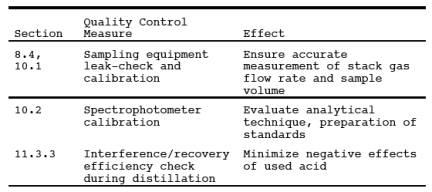
9.0 Quality Control.
9.1 Miscellaneous
Quality Control Measures.
9.2 Volume Metering
System Checks. Same as Method 5, Section 9.2.
10.0 Calibration and Standardization.
NOTE: Maintain a laboratory log of all calibrations.
10.1 Sampling Equipment.
Calibrate the probe
nozzle, pitot tube, metering system, probe heater, temperature sensors, and
barometer according to the procedures outlined in Method 5, Sections 10.1 through 10.6. Conduct
the leak-check of the metering system according to the procedures outlined in Method 5, Section 8.4.1.
10.2 Spectrophotometer.
10.2.1 Prepare the
blank standard by adding 10 ml of SPADNS mixed reagent to 50 ml of water.
10.2.2 Accurately
prepare a series of standards from the 0.01 mg F-/ml standard
fluoride solution (Section 860 7.3.10) by diluting 0, 2, 4, 6, 8, 10, 12, and
14 ml to 100 ml with deionized, distilled water. Pipet 50 ml from each
solution, and transfer each to a separate 100-ml beaker. Then add 10 ml of
SPADNS mixed reagent (Section 7.3.13) to each. These standards will contain 0,
10, 20, 30, 40, 50, 60, and 70 µg F- (0 to 1.4
µg/ml), respectively.
10.2.3 After mixing,
place the blank and calibration standards in a constant temperature bath for 30
minutes before reading the absorbance with the spectrophotometer. Adjust all
samples to this same temperature before analyzing.
10.2.4 With the
spectrophotometer at 570 nm, use the blank standard to set the absorbance to
zero. Determine the absorbance of the standards.
10.2.5 Prepare a
calibration curve by plotting µg F-/50 ml
versus absorbance on linear graph paper. Prepare the standard curve initially
and thereafter whenever the SPADNS mixed reagent is newly made. Also, run a
calibration standard with each set of samples and, if it differs from the
calibration curve by more than ±2 percent, prepare a new standard curve.
11.0 Analytical Procedures.
11.1 Sample Loss Check.
Note the liquid
levels in Containers No. 1 and No. 2, determine whether leakage occurred during
transport, and note this finding on the analytical data sheet. If noticeable
leakage has occurred, either void the sample or use methods, subject to the
approval of the Administrator, to correct the final results.
11.2 Sample Preparation.
Treat the contents of
each sample container as described below:
11.2.1 Container No.
1 (Probe, Filter, and Impinger Catches). Filter this container's contents,
including the sampling filter, through Whatman No. 541 filter paper, or
equivalent, into a 1500-ml beaker.
11.2.1.1 If the filtrate
volume exceeds 900 ml, make the filtrate basic (red to phenolphthalein) with
NaOH, and evaporate to less than 900 ml.
11.2.1.2 Place the
filtered material (including sampling filter) in a nickel crucible, add a few
ml of water, and macerate the filters with a glass rod.
11.2.1.2.1 Add 100 mg
CaO to the crucible, and mix the contents thoroughly to form a slurry. Add two
drops of phenolphthalein indicator. Place the crucible in a hood under infrared
lamps or on a hot plate at low heat. Evaporate the water completely. During the
evaporation of the water, keep the slurry basic (red to phenolphthalein) to
avoid loss of F-. If the indicator turns colorless (acidic)
during the evaporation, add CaO until the color turns red again.
11.2.1.2.2 After
evaporation of the water, place the crucible on a hot plate under a hood, and
slowly increase the temperature until the Whatman No. 541 and sampling filters
char. It may take several hours to char the filters completely.
11.2.1.2.3 Place the
crucible in a cold muffle furnace. Gradually (to prevent smoking) increase the
temperature to 600 ˚C (1100 ˚F), and maintain this temperature until the
contents are reduced to an ash. Remove the crucible from the furnace, and allow
to cool.
11.2.1.2.4 Add approximately
4 g of crushed NaOH to the crucible, and mix. Return the crucible to the muffle
furnace, and fuse the sample for 10 minutes at 600 ˚C.
11.2.1.2.5 Remove the
sample from the furnace, and cool to ambient temperature. Using several
rinsings of warm water, transfer the contents of the crucible to the beaker
containing the filtrate. To ensure complete sample removal, rinse finally with
two 20-ml portions of 25 percent H2SO4, and carefully add to the beaker. Mix well, and transfer to a
1-liter volumetric flask. Dilute to volume with water, and mix thoroughly.
Allow any undissolved solids to settle.
11.2.2 Container No.
2 (Sample Blank). Treat in the same manner as described in Section 11.2.1
above.
11.2.3 Adjustment of
Acid/Water Ratio in Distillation Flask. Place 400 ml of water in the
distillation flask, and add 200 ml of concentrated H2SO4. Add some soft glass beads and several small
pieces of broken glass tubing, and assemble the apparatus as shown in Figure
13A-2. Heat the flask until it reaches a temperature of 175 ˚C (347 ˚F) to
adjust the acid/water ratio for subsequent distillations. Discard the
distillate. CAUTION: Use a
protective shield when carrying out this procedure. Observe standard
precautions when mixing H2SO4 with
water. Slowly add the acid to the flask with constant swirling.
11.3 Distillation.
11.3.1 Cool the
contents of the distillation flask to below 80 ˚C (180 ˚F). Pipet an aliquot of
sample containing less than 10.0 mg F- directly
into the distillation flask, and add water to make a total volume of 220 ml
added to the distillation flask. (To estimate the appropriate aliquot size,
select an aliquot of the solution, and treat as described in Section 11.4.1.
This will be an approximation of the F- content
because of possible interfering ions.)
NOTE: If the sample contains chloride, add 5 mg of
Ag2SO4 to the
flask for every mg of chloride.
11.3.2 Place a 250-ml
volumetric flask at the condenser exit. Heat the flask as rapidly as possible
with a Bunsen burner, and collect all the distillate up to 175 ˚C (347 ˚F).
During heatup, play the burner flame up and down the side of the flask to
prevent bumping. Conduct the distillation as rapidly as possible (15 minutes or
less). Slow distillations have been found to produce low F- recoveries. Be
careful not to exceed 175 ˚C (347 ˚F) to avoid causing H2SO4 to distill over. If F- distillation in the mg range is to be followed by a distillation in
the fractional mg range, add 220 ml of water and distill it over as in the acid
adjustment step to remove residual F- from the
distillation system.
11.3.3 The acid in
the distillation flask may be used until there is carry-over of interferences
or poor F- recovery. Check for interference and for recovery efficiency every
tenth distillation using a water blank and a standard solution. Change the acid
whenever the F- recovery is less than 90 percent or the blank value exceeds 0.1
µg/ml.
11.4 Sample Analysis.
11.4.1 Containers No.
1 and No. 2.
11.4.1.1 After
distilling suitable aliquots from Containers No. 1 and No. 2 according to
Section 11.3, dilute the distillate in the volumetric flasks to exactly 250 ml
with water, and mix thoroughly. Pipet a suitable aliquot of each sample
distillate (containing 10 to 40 µg F-/ml) into
a beaker, and dilute to 50 ml with water. Use the same aliquot size for the
blank. Add 10 ml of SPADNS mixed reagent (Section
7.3.13), and mix thoroughly.
11.4.1.2 After
mixing, place the sample in a constant-temperature bath containing the standard
solutions for 30 minutes before reading the absorbance on the
spectrophotometer.
NOTE: After the sample and colorimetric reagent are
mixed, the color formed is stable for approximately 2 hours. Also, a 3 ˚C (5.4
˚F) temperature difference between the sample and standard solutions produces
an error of approximately 0.005 mg F-/liter. To
avoid this error, the absorbencies of the sample and standard solutions must be
measured at the same temperature.
11.4.1.3 Set the spectrophotometer
to zero absorbance at 570 nm with the zero reference solution (Section 7.3.12),
and check the spectrophotometer calibration with the standard solution (Section
7.3.10). Determine the absorbance of the samples, and determine the concentration
from the calibration curve. If the concentration does not fall within the range
of the calibration curve, repeat the procedure using a different size aliquot.
11.4.2
Container No. 3 (Silica Gel). Weigh the spent silica gel (or silica gel plus
impinger) to the nearest 0.5 g
using a balance. This step may be conducted in the field.
12.0 Data Analysis and Calculations.
Carry out
calculations, retaining at least one extra significant figure beyond that of
the acquired data. Round off figures after final calculation. Other forms of
the equations may be used, provided that they yield equivalent results.
Ad = Aliquot of distillate taken for color development, ml.
At = Aliquot of total sample added to still, ml.
Bws = Water vapor in the gas stream, portion by
volume.
Cs = Concentration of F- in stack gas, mg/dscm
(gr/dscf).
Fc = F- concentration from the calibration curve, µg.
Ft = Total F-
in sample, mg.
Tm = Absolute average dry gas meter (DGM) temperature (see Figure 5-3 of Method 5), ˚K (˚R).
Ts = Absolute average stack gas temperature (see Figure 5-3 of Method
5), ˚K (˚R).
Vd = Volume of distillate as diluted, ml.
Vm(std) = Volume of gas sample as measured by DGM at
standard conditions, dscm (dscf).
Vt = Total volume of F- sample, after final
dilution, ml.
Vw(std) = Volume of water vapor in the gas sample at
standard conditions, scm (scf)
12.2 Average DGM
Temperature and Average Orifice Pressure Drop (see Figure 5-3 of Method 5).
12.3 Dry Gas Volume.
Calculate Vm(std), and adjust for leakage, if necessary, using Equation 5-1 of Method 5.
12.4 Volume of Water
Vapor and Moisture Content. Calculate Vw(std) and
Bws from the data obtained in this method. Use Equations
5-2 and 5-3 of Method 5.
12.5 Total Fluoride
in Sample. Calculate the amount of F- in the
sample using the following equation:
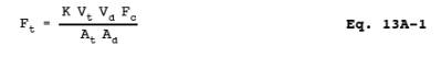
where:
K = 10-3 mg/µg (metric units)
= 1.54 x 10⁻⁵ gr/µg (English units)
12.6 Fluoride Concentration
in Stack Gas. Determine the F- concentration in the
stack gas using the following equation:
12.7 Isokinetic
Variation. Same as Method 5, Section 12.11.
13.0 Method Performance.
The following
estimates are based on a collaborative test done at a primary aluminum smelter.
In the test, six laboratories each sampled the stack simultaneously using two
sampling trains for a total of 12 samples per sampling run. Fluoride
concentrations encountered during the test ranged from 0.1 to 1.4 mg F-/m3.
13.1 Precision. The
intra- and inter-laboratory standard deviations, which include sampling and
analysis errors, were 0.044 mg F-/m3 with 60 degrees of freedom and 0.064 mg F-/m3 with five degrees of freedom, respectively.
13.2 Bias. The
collaborative test did not find any bias in the analytical method.
13.3 Range. The range
of this method is 0 to 1.4 µg F-/ml.
14.0 Pollution Prevention. [Reserved]
15.0 Waste Management. [Reserved]
16.0 Alternative Procedures.
16.1 Compliance with
ASTM D 3270-73T, 80, 91, or 95 (incorporated by reference - see § 60.17) "Analysis of Fluoride Content of the
Atmosphere and Plant Tissues (Semi-automated Method) is an acceptable alternative
for the requirements specified in Sections 11.2, 11.3, and 11.4.1 when applied
to suitable aliquots of Containers 1 and 2 samples.
17.0 References.
1. Bellack, Ervin.
Simplified Fluoride Distillation Method. J. of the American Water Works Association.
50:5306. 1958.
2. Mitchell, W.J.,
J.C. Suggs, and F.J. Bergman. Collaborative Study of EPA Method 13A and Method
13B. Publication No. EPA-300/4-77-050. U.S. Environmental Protection Agency,
Research Triangle Park, NC. December 1977.
3. Mitchell, W.J.,
and M.R. Midgett. Adequacy of Sampling Trains and Analytical Procedures Used
for Fluoride. Atm. Environ. 10:865-872. 1976.
18.0 Tables, Diagrams, Flowcharts, and Validation Data.
Figure
13A-1. Fluoride Sampling Train.
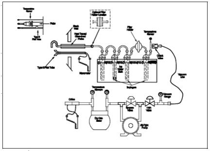
Figure
13A-2. Fluoride Distillation Apparatus.