METHOD 104 -
DETERMINATION OF BERYLLIUM EMISSIONS FROM STATIONARY SOURCES
NOTE: This method does not include all of the specifications
(e.g., equipment and
supplies) and procedures (e.g.,
sampling and analytical) essential to its performance. Some material is
incorporated by reference from methods in Appendix A to 40 CFR part 60.
Therefore, to obtain reliable results, persons using this method should have a
thorough knowledge of at least the following additional test methods: Method 1, Method 2, Method 3, and Method 5 in
Appendix A, Part 60.
7.3 Sample Preparation
and Analysis.
8.0 Sample Collection,
Preservation, Transport, and Storage.
8.2 Preliminary
Determinations.
8.3 Preparation of
Sampling Train.
8.4 Leak Check
Procedures, Sampling Train Operation, and Calculation of Percent Isokinetic.
8.7 Post-test Glassware
Rinsing.
10.0 Calibration and
Standardization.
10.2 Preparation of
Standard Solutions.
10.3 Spectrophotometer
and Recorder.
10.5 Spectrophotometer
Calibration Quality Control.
11.4 Spectrophotometer
Preparation.
11.6 Container No. 2
(Silica Gel).
12.0 Data Analysis and
Calculations.
13.0 Method
Performance. [Reserved]
14.0 Pollution
Prevention. [Reserved]
15.0 Waste Management.
[Reserved]
17.0 Tables, Diagrams,
Flowcharts, And Validation Data.
[Reserved]
1.0 Scope and Application.
1.1 Analytes.
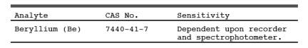
1.2 Applicability.
This method is
applicable for the determination of Be emissions in ducts or stacks at
stationary sources. Unless otherwise specified, this method is not intended to
apply to gas streams other than those emitted directly to the atmosphere
without further processing.
1.3 Data Quality Objectives.
Adherences to the
requirements of this method will enhance the quality of the data obtained from
air pollutant sampling methods.
2.0 Summary of Method.
2.1 Particulate and
gaseous Be emissions are withdrawn isokinetically from the source and are
collected on a glass fiber filter and in water. The collected sample is digested
in an acid solution and is analyzed by atomic absorption spectrophotometry.
3.0 Definitions. [Reserved]
4.0 Interferences.
4.1 Matrix Effects.
Analysis for Be by
flame atomic absorption spectrophotometry is sensitive to the chemical
composition and to the physical properties (e.g., viscosity, pH) of the sample. Aluminum and
silicon in particular are known to interfere when present in appreciable
quantities. The analytical procedure includes (optionally) the use of the
Method of Standard Additions to check for these matrix effects, and sample
analysis using the Method of Standard Additions if significant matrix effects
are found to be present (see Reference 2 in Section 16.0).
5.0 Safety.
5.1 Disclaimer.
This method may
involve hazardous materials, operations, and equipment. This test method may
not address all of the safety problems associated with its use. It is the
responsibility of the user of this test method to establish appropriate safety
and health practices and determine the applicability of regulatory limitations
prior to performing this test method.
5.2 Corrosive reagents.
The following
reagents are hazardous. Personal protective equipment and safe procedures are
useful in preventing chemical splashes. If contact occurs, immediately flush
with copious amounts of water at least 15 minutes. Remove clothing under shower
and decontaminate. Treat residual chemical burn as thermal burn.
5.2.1 Hydrochloric
Acid (HCl). Highly toxic. Vapors are highly irritating to eyes, skin, nose, and
lungs, causing severe damage. May cause bronchitis, pneumonia, or edema of
lungs. Exposure to concentrations of 0.13 to 0.2 percent can be lethal to
humans in a few minutes. Provide ventilation to limit exposure. Reacts with metals,
producing hydrogen gas.
5.2.2 Hydrogen
Peroxide (H2O2). Irritating to eyes,
skin, nose, and lungs.
5.2.3 Nitric Acid
(HNO3). Highly corrosive to eyes, skin, nose, and
lungs. Vapors cause bronchitis, pneumonia, or edema of lungs. Reaction to
inhalation may be delayed as long as 30 hours and still be fatal. Provide
ventilation to limit exposure. Strong oxidizer. Hazardous reaction may occur
with organic materials such as solvents.
5.2.4 Sodium
Hydroxide (NaOH). Causes severe damage to eyes and skin. Inhalation causes
irritation to nose, throat, and lungs. Reacts exothermically with limited
amounts of water.
5.3 Beryllium
Beryllium is
hazardous, and precautions should be taken to minimize exposure.
6.0 Equipment and Supplies.
6.1 Sample Collection.
Same as Method 5, Section 6.1, with the exception of the following:
6.1.1 Sampling Train.
Same as Method 5, Section 6.1.1, with the exception of the following:
6.1.2 Probe Liner.
Borosilicate or quartz glass tubing. A heating system capable of maintaining a gas
temperature of 120 ± 14 ºC (248 ± 25 ºF) at the probe exit during sampling to
prevent water condensation may be used.
NOTE: Do not use metal probe liners.
6.1.3 Filter Holder.
Borosilicate glass, with a glass frit filter support and a silicone rubber
gasket. Other materials of construction (e.g., stainless steel, Teflon, Viton) may be used,
subject to the approval of the Administrator. The holder design shall provide a
positive seal against leakage from the outside or around the filter. The holder
shall be attached immediately at the outlet of the probe. A heating system
capable of maintaining the filter at a minimum temperature in the range of the
stack temperature may be used to prevent condensation from occurring.
6.1.4 Impingers. Four
Greenburg-Smith impingers connected in series with leak-free ground glass
fittings or any similar leak-free noncontaminating fittings. For the first,
third, and fourth impingers, use impingers that are modified by replacing the
tip with a 13 mm-ID (0.5 in.) glass tube extending to 13 mm (0.5 in.) from the
bottom of the flask may be used.
6.2 Sample Recovery.
The following items
are needed for sample recovery:
6.2.1 Probe Cleaning
Rod. At least as long as probe.
6.2.2 Glass Sample
Bottles. Leakless, with Teflon-lined caps, 1000 ml.
6.2.3 Petri Dishes.
For filter samples, glass or polyethylene, unless otherwise specified by the
Administrator.
6.2.4 Graduated
Cylinder. 250 ml.
6.2.5 Funnel and
Rubber Policeman. To aid in transfer of silica gel to container; not necessary
if silica gel is weighed in the field.
6.2.6 Funnel. Glass,
to aid in sample recovery.
6.2.7 Plastic Jar.
Approximately 300 ml.
6.3 Analysis.
The following items
are needed for sample analysis:
6.3.1 Atomic Absorption
Spectrophotometer. Perkin-Elmer 303, or equivalent, with nitrous
oxide/acetylene
burner.
6.3.2 Hot Plate.
6.3.3 Perchloric Acid
Fume Hood.
7.0 Reagents and Standards.
NOTE: Unless otherwise indicated, it is intended that
all reagents conform to the specifications established by the Committee on
Analytical Reagents of the American Chemical Society, where such specifications
are available; otherwise, use the best available grade.
7.1 Sample Collection.
Same as Method 5, Section 7.1, including deionized distilled water conforming
to ASTM D 1193-77 or 91 (incorporated by reference - see §61.18), Type 3. The
Millipore AA filter is recommended.
7.2 Sample Recovery.
Same as Method 5 in
Appendix A, Part 60, Section 7.2, with the addition of the following:
7.2.1 Wash Acid, 50
Percent (V/V) Hydrochloric Acid (HCl). Mix equal volumes of concentrated HCl
and water, being careful to add the acid slowly to the water.
7.3 Sample Preparation and Analysis.
The following
reagents and standards and standards are needed for sample preparation and
analysis:
7.3.1 Water. Same as
in Section 7.1.
7.3.2. Perchloric
Acid (HClO4). Concentrated (70 percent V/V).
7.3.3 Nitric Acid
(HNO3). Concentrated.
7.3.4 Beryllium
Powder. Minimum purity 98 percent.
7.3.5 Sulfuric Acid
(H2SO4)
Solution, 12 N. Dilute 33 ml of concentrated H2SO4 to 1 liter with water.
7.3.6 Hydrochloric
Acid Solution, 25 Percent HCl (V/V).
7.3.7 Stock Beryllium
Standard Solution, 10 µg Be/ml. Dissolve 10.0 mg of Be in 80 ml of 12 N H2SO4 in a 1000-ml volumetric flask. Dilute to volume
with water. This solution is stable for at least one month. Equivalent strength
Be stock solutions may be prepared from Be salts such as BeCl2 and Be(NO3)2 (98 percent minimum
purity).
7.3.8 Working
Beryllium Standard Solution, 1 µg Be/ml. Dilute a 10 ml aliquot of the stock
beryllium standard solution to 100 ml with 25 percent HCl solution to give a
concentration of 1 mg/ml. Prepare this dilute stock solution fresh daily.
8.0 Sample Collection, Preservation, Transport, and Storage.
The amount of Be that
is collected is generally small, therefore, it is necessary to exercise
particular care to prevent contamination or loss of sample.
8.1 Pretest Preparation.
Same as Method 5, Section 8.1, except omit Section
8.1.3.
8.2 Preliminary Determinations.
Same as Method 5, Section 8.2, with the exception of the
following:
8.2.1 Select a nozzle
size based on the range of velocity heads to assure that it is not necessary to
change the nozzle size in order to maintain isokinetic sampling rates below 28
liters/min (1.0 cfm).
8.2.2 Obtain samples
over a period or periods of time that accurately determine the maximum
emissions that occur in a 24-hour period. In the case of cyclic operations,
perform sufficient sample runs for the accurate determination of the emissions
that occur over the duration of the cycle. A minimum sample time of 2 hours per
run is recommended.
8.3 Preparation of Sampling Train.
Same as Method 5, Section 8.3, with the exception of the
following:
8.3.1
Prior to assembly, clean all glassware (probe, impingers, and connectors) by
first soaking in wash acid for 2 hours, followed by rinsing with water.
8.3.2 Save a portion
of the water for a blank analysis.
8.3.3 Procedures
relating to the use of metal probe liners are not applicable.
8.3.4 Probe and
filter heating systems are needed only if water condensation is a problem. If
this is the case, adjust the heaters to provide a temperature at or above the
stack temperature. However, membrane filters such as the Millipore AA are limited
to about 107 ºC (225 ºF). If the stack gas is in excess of about 93 ºC (200
ºF), consideration should be given to an alternate procedure such as moving the
filter holder downstream of the first impinger to insure that the filter does
not exceed its temperature limit. After the sampling train has been assembled,
turn on and set the probe heating system, if applicable, at the desired
operating temperature. Allow time for the temperatures to stabilize. Place
crushed ice around the impingers.
NOTE: An empty impinger may be inserted between the
third impinger and the silica gel to remove excess moisture from the sample
stream.
8.4 Leak Check Procedures, Sampling Train Operation, and Calculation of Percent Isokinetic.
Same as Method 5, Sections 8.4, 8.5, and 8.6,
respectively.
8.5 Sample Recovery.
Same as Method 5, Section 8.7, except treat the sample
as follows: Transfer the probe and impinger assembly to a cleanup area that is
clean, protected from the wind, and free of Be contamination. Inspect the train
before and during this assembly, and note any abnormal conditions. Treat the
sample as follows: Disconnect the probe from the impinger train.
8.5.1 Container No.
1. Same as Method 5, Section 8.7.6.1.
8.5.2 Container No.
2. Place the contents (measured to 1 ml) of the first three impingers into a
glass sample bottle. Use the procedures outlined in Section 8.7.6.2 of Method 5, where
applicable, to rinse the probe nozzle, probe fitting, probe liner, filter
holder, and all glassware between the filter holder and the back half of the third
impinger with water. Repeat this procedure with acetone. Place both water and
acetone rinse solutions in the sample bottle with the contents of the
impingers.
8.5.3 Container No.
3. Same as Method 5, Section 8.7.6.3.
8.6 Blanks.
8.6.1 Water Blank.
Save a portion of the water as a blank. Take 200 ml directly from the wash
bottle being used and place it in a plastic sample container labeled "H2O blank."
8.6.2 Filter. Save
two filters from each lot of filters used in sampling. Place these filters in a
container labeled "filter blank."
8.7 Post-test Glassware Rinsing.
If an additional test
is desired, the glassware can be carefully double rinsed with water and
reassembled. However, if the glassware is out of use more than 2 days, repeat
the initial acid wash procedure.
9.0 Quality Control.
9.1 Miscellaneous
Quality Control Measures. Section
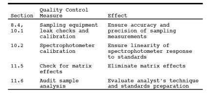
9.2 Volume Metering
System Checks. Same as Method 5, Section 9.2.
10.0 Calibration and Standardization.
NOTE: Maintain a laboratory log of all calibrations.
10.1 Sampling Equipment.
Same as Method 5, Section 10.0.
10.2 Preparation of Standard Solutions.
Pipet 1, 3, 5, 8, and
10 ml of the 1.0 µg Be/ml working standard solution into separate 100 ml
volumetric flasks, and dilute to the mark with water. The total amounts of Be
in these standards are 1, 3, 5, 8, and 10 µg, respectively.
10.3 Spectrophotometer and Recorder.
The Be response may
be measured by either peak height or peak area. Analyze an aliquot of the 10-µg
standard at 234.8 nm using a nitrous oxide/acetylene flame. Determine the
maximum absorbance of the standard, and set this value to read 90 percent of
the recorder full scale.
10.4 Calibration Curve.
10.4.1 After setting
the recorder scale, analyze an appropriately sized aliquot of each standard and
the BLANK (see Section 11) until two consecutive peaks agree within 3 percent
of their average value.
10.4.3 Subtract the
average peak height (or peak area) of the blank - which must be less than 2
percent of recorder full scale - from the averaged peak heights of the
standards. If the blank absorbance is greater than 2 percent of full-scale, the
probable cause is Be contamination of a reagent or carry-over of Be from a
previous sample. Prepare the calibration curve by plotting the corrected peak
height of each standard solution versus the corresponding total Be weight in
the standard (in µg).
10.5 Spectrophotometer Calibration Quality Control.
Calculate the least
squares slope of the calibration curve. The line must pass through the origin
or through a point no further from the origin than ±2 percent of the recorder
full scale. Multiply the corrected peak height by the reciprocal of the least
squares slope to determine the distance each calibration point lies from the
theoretical calibration line. The difference between the calculated
concentration values and the actual concentrations (i.e., 1, 3, 5, 8, and 10 µg Be) must be less than 7
percent for all standards.
11.0 Analytical Procedure.
11.1 Sample Loss Check.
Prior to analysis,
check the liquid level in Container No. 2. Note on the analytical data sheet
whether leakage occurred during transport. If a noticeable amount of leakage
occurred, either void the sample or take steps, subject to the approval of the
Administrator, to adjust the final results.
11.2 Glassware Cleaning.
Before use, clean all
glassware according to the procedure of Section 8.3.1.
11.3 Sample Preparation.
The digestion of Be
samples is accomplished in part in concentrated HClO4.
NOTE: The sample must be heated to light brown fumes
after the initial HNO3
addition; otherwise, dangerous perchlorates
may result from the subsequent HClO4 digestion.
HClO4 should be used only under a hood.
11.3.1 Container No.
1. Transfer the filter and any loose particulate matter from Container No. 1 to
a 150-ml beaker. Add 35 ml concentrated HNO3. To oxidize
all organic matter, heat on a hotplate until light brown fumes are evident.
Cool to room temperature, and add 5 ml 12 N H2SO4 and 5 ml concentrated HClO4.
11.3.2 Container No.
2. Place a portion of the water and acetone sample into a 150 ml beaker, and
put on a hotplate. Add portions of the remainder as evaporation proceeds and
evaporate to dryness. Cool the residue, and add 35 ml concentrated HNO3. To oxidize all organic matter, heat on a hotplate until light
brown fumes are evident. Cool to room temperature, and add 5 ml 12 N H2SO4 and 5 ml concentrated HClO4. Then proceed with step 11.3.4.
11.3.3 Final Sample
Preparation. Add the sample from Section 11.3.2 to the 150-ml beaker from
Section 11.3.1. Replace on a hotplate, and evaporate to dryness in a HClO4 hood. Cool the residue to room temperature, add 10.0 ml of 25
percent V/V HCl, and mix to dissolve the residue.
11.3.4 Filter and
Water Blanks. Cut each filter into strips, and treat each filter individually
as directed in Section 11.3.1. Treat the 200-ml water blank as directed in
Section 11.3.2. Combine and treat these blanks as directed in Section 11.3.3.
11.4 Spectrophotometer Preparation.
Turn on the power;
set the wavelength, slit width, and lamp current; and adjust the background
corrector as instructed by the manufacturer's manual for the particular atomic
absorption spectrophotometer. Adjust the burner and flame characteristics as
necessary.
11.5 Analysis.
Calibrate the
analytical equipment and develop a calibration curve as outlined in Sections
10.4 and 10.5.
11.5.1 Beryllium
Samples. Repeat the procedure used to establish the calibration curve with an
appropriately sized aliquot of each sample (from Section 11.3.3) until two
consecutive peak heights agree within 3 percent of their average value. The
peak height of each sample must be greater than 10 percent of the recorder full
scale. If the peak height of the sample is off scale on the recorder, further
dilute the original source sample to bring the Be concentration into the
calibration range of the spectrophotometer.
11.5.2 Run a blank
and standard at least after every five samples to check the spectrophotometer
calibration. The peak height of the blank must pass through a point no further
from the origin than ±2 percent of the recorder full scale. The difference
between the measured concentration of the standard (the product of the
corrected peak height and the reciprocal of the least squares slope) and the
actual concentration of the standard must be less than 7 percent, or recalibration
of the analyzer is required.
11.5.3 Check for
Matrix Effects (optional). Use the Method of Standard Additions (see Reference
2 in Section 16.0) to check at least one sample from
each source for matrix effects on the Be results. If the results of the Method
of Standard Additions procedure used on the single source sample do not agree
to within 5 percent of the value obtained by the routine atomic absorption
analysis, then reanalyze all samples from the source using the Method of
Standard Additions procedure.
11.6 Container No. 2 (Silica Gel).
Weigh the spent
silica gel (or silica gel plus impinger) to the nearest 0.5 g using a balance.
(This step may be conducted in the field.)
12.0 Data Analysis and Calculations.
Carry out
calculations, retaining at least one extra decimal significant figure beyond
that of the acquired data. Round off figures only after the final calculation.
Other forms of the equations may be used as long as they give equivalent
results.
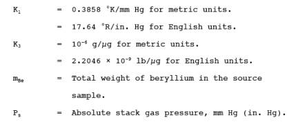
12.1 Nomenclature.
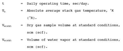
12.2 Average Dry Gas
Meter Temperature and Average Orifice Pressure Drop, Dry Gas Volume, Volume of
Water Vapor Condensed, Moisture Content, Isokinetic Variation, and Stack Gas
Velocity and Volumetric Flow Rate. Same as Method
5, Sections 12.2 through 12.5, 12.11, and 12.12, respectively.
12.3 Total Beryllium.
For each source sample, correct the average maximum absorbance of the two
consecutive samples whose peak heights agree within 3 percent of their average
for the contribution of the solution blank (see Sections 11.3.4 and 11.5.2).
Correcting for any dilutions if necessary, use the calibration curve and these
corrected averages to determine the total weight of Be in each source sample.
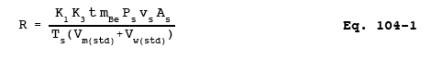
12.4 Beryllium
Emission Rate. Calculate the daily Hg emission rate, R, using Equation 104-1.
For continuous operations, the operating time is equal to 86,400 seconds per
day. For cyclic operations, use only the time per day each stack is in
operation. The total Hg emission rate from a source will be the summation of
results from all stacks.
12.5 Determination of
Compliance. Each performance test consists of three sample runs. For the
purpose of determining compliance with an applicable national emission
standard, use the average of the results of all sample runs.
13.0 Method Performance. [Reserved]
14.0 Pollution Prevention. [Reserved]
15.0 Waste Management. [Reserved]
16.0 References.
Same as References 1,
2, and 4-11 of Section 16.0 of Method 101
with the addition of the following:
1. Amos, M.D., and
J.B. Willis. Use of High-Temperature Pre-Mixed Flames in Atomic Absorption
Spectroscopy. Spectrochim. Acta. 22:1325. 1966.
2. Fleet, B., K.V.
Liberty, and T. S. West. A Study of Some Matrix Effects in the Determination of
Beryllium by Atomic Absorption Spectroscopy in the Nitrous Oxide-Acetylene
Flame. Talanta 17:203. 1970.
17.0 Tables, Diagrams, Flowcharts, And Validation Data. [Reserved]