METHOD 102 -
DETERMINATION OF PARTICULATE AND GASEOUS MERCURY EMISSIONS FROM CHLOR-ALKALI
PLANTS (HYDROGEN STREAMS)
NOTE: This method does not include all of the
specifications (e.g.,
equipment and supplies) and procedures (e.g., sampling and analytical) essential to its
performance. Some material is incorporated by reference from other methods in
this part and in Appendix A to 40 CFR Part 60. Therefore, to obtain reliable
results, persons using this method should have a thorough knowledge of at least
the following additional test methods: Method 1, Method 2, Method 3, Method 5, and Method 101.
8.0 Sample Collection,
Preservation, Transport, and Storage.
8.1 Setting of
Isokinetic Rates.
8.2 Sampling in Small
(<12-in. Diameter) Stacks.
10.0 Calibration and
Standardizations.
12.0 Data Analysis and
Calculations.
14.0 Pollution
Prevention. [Reserved]
15.0 Waste Management.
[Reserved]
17.0 Tables, Diagrams,
Flowcharts, and Validation Data.
1.0 Scope and Application.
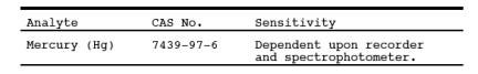
1.1 Analytes.
1.2 Applicability.
This method is
applicable for the determination of Hg emissions, including both particulate
and gaseous Hg, from chlor-alkali plants and other sources (as specified in the
regulations) where the carrier-gas stream in the duct or stack is principally
hydrogen.
1.3 Data Quality Objectives.
Adherence to the
requirements of this method will enhance the quality of the data obtained from
air pollutant sampling methods.
2.0 Summary of Method.
2.1 Particulate and
gaseous Hg emissions are withdrawn isokinetically from the source and collected
in acidic iodine monochloride (ICl) solution. The Hg collected (in the mercuric
form) is reduced to elemental Hg, which is then aerated from the solution into
an optical cell and measured by atomic absorption spectrophotometry.
3.0 Definitions. [Reserved]
4.0 Interferences.
Same as Method 101, Section 4.2.
5.0 Safety.
5.1 Disclaimer.
This method may
involve hazardous materials, operations, and equipment. This test method may
not address all of the safety problems associated with its use. It is the
responsibility of the user of this test method to establish appropriate safety
and health practices and determine the applicability of regulatory limitations
prior to performing this test method.
5.2 Corrosive Reagents.
Same as Method 101, Section 5.2.
5.3 Explosive Mixtures.
The sampler must conduct
the source test under conditions of utmost safety because hydrogen and air
mixtures are explosive. Since the sampling train essentially is leakless,
attention to safe operation can be concentrated at the inlet and outlet. If a
leak does occur, however, remove the meter box cover to avoid a possible
explosive mixture. The following specific precautions are recommended:
5.3.1 Operate only
the vacuum pump during the test. The other electrical equipment, e.g., heaters,
fans, and timers, normally are not essential to the success of a hydrogen
stream test.
5.3.2 Seal the sample
port to minimize leakage of hydrogen from the stack.
5.3.3 Vent sampled
hydrogen at least 3 m (10 ft) away from the train. This can be accomplished by attaching
a 13-mm (0.50-in.) ID Tygon tube to the exhaust from the orifice meter.
NOTE: A smaller ID tubing may cause the orifice
meter calibration to be erroneous. Take care to ensure that the exhaust line is
not bent or pinched.
6.0 Equipment and Supplies.
Same as Method 101, Section 6.0, with the exception of
the following:
6.1 Probe Heating
System. Do not use, unless otherwise specified.
6.2 Glass Fiber
Filter. Do not use, unless otherwise specified.
7.0 Reagents and Standards.
Same as Method 101, Section 7.0.
8.0 Sample Collection, Preservation, Transport, and Storage.
Same as Method 101, Section 8.0, with the exception of
the following:
8.1 Setting of Isokinetic Rates.
8.1.1 If a nomograph
is used, take special care in the calculation of the molecular weight of the
stack gas and in the setting of the nomograph to maintain isokinetic conditions
during sampling (Sections 8.1.1.1 through 8.1.1.3 below).
8.1.1.1 Calibrate the
meter box orifice. Use the techniques described in APTD-0576 (see Reference 9
in Section 17.0 of Method 5). Calibration of
the orifice meter at flow conditions that simulate the conditions at the source
is suggested. Calibration should either be done with hydrogen or with some
other gas having similar Reynolds Number so that there is similarity between
the Reynolds Numbers during calibration and during sampling.
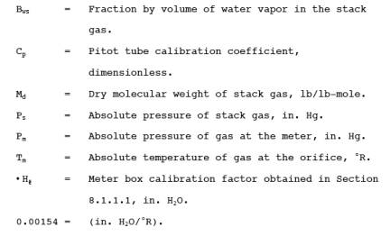
8.1.1.2 The nomograph
described in APTD-0576 cannot be used to calculate the C factor because the
nomograph is designed for use when the stack gas dry molecular weight is 29 ±
4. Instead, the following calculation should be made to determine the proper C
factor:
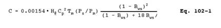
where:
NOTE: This calculation is left in English units, and
is not converted to metric units because nomographs are based on English units.
8.1.1.3 Set the
calculated C factor on the operating nomograph, and select the proper nozzle diameter
and K factor as specified in APTD-0576. If the C factor obtained in Section
8.1.1.2 exceeds the values specified on the existing operating nomograph,
expand the C scale logarithmically so that the values can be properly located.
8.1.2 If a calculator
is used to set isokinetic rates, it is suggested that the isokinetic equation
presented in Reference 13 in Section 17.0 of
Method 101 be consulted.
8.2 Sampling in Small (<12-in. Diameter) Stacks.
When the stack
diameter (or equivalent diameter) is less than 12 inches, conventional pitot
tube-probe assemblies should not be used. For sampling guidelines, see
Reference 14 in Section 17.0 of Method 101.
9.0 Quality Control.
Same as Method 101, Section 9.0.
10.0 Calibration and Standardizations.
Same as Method 101, Section 10.0.
11.0 Analytical Procedure.
Same as Method 101, Section 11.0.
12.0 Data Analysis and Calculations.
Same as Method 101, Section 12.0.
13.0 Method Performance.
Same as Method 101, Section 13.0.
13.1 Analytical
Range. After initial dilution, the range of this method is 0.5 to 120 µg Hg/ml.
The upper limit can be extended by further dilution of the sample.
14.0 Pollution Prevention. [Reserved]
15.0 Waste Management. [Reserved]
16.0 References.
Same as Method 101, Section 16.0.
17.0 Tables, Diagrams, Flowcharts, and Validation Data.
[Reserved]