METHOD 7C -
DETERMINATION OF NITROGEN OXIDE EMISSIONS FROM STATIONARY SOURCES (ALKALINE
PERMANGANATE/COLORIMETRIC METHOD)
NOTE: This method does not include all of the
specifications (e.g., equipment
and supplies) and procedures (e.g.,
sampling and analytical) essential to its performance. Some material is
incorporated by reference from other methods in this part. Therefore, to obtain
reliable results, persons using this method should have a thorough knowledge of
at least the following additional test methods: Method
1, Method 3, Method 6
and Method 7.
6.1 Sample Collection
and Sample Recovery.
6.2 Sample Preparation
and Analysis.
7.2 Sample Preparation
and Analysis.
8.0 Sample Collection,
Preservation, Storage, and Transport.
8.1 Preparation of
Sampling Train.
10.0 Calibration and
Standardizations.
12.0 Data Analysis and
Calculations.
14.0 Pollution
Prevention. [Reserved]
15.0 Waste Management.
[Reserved]
17.0 Tables, Diagrams,
Flowcharts, and Validation Data.
1.0 Scope and Application.
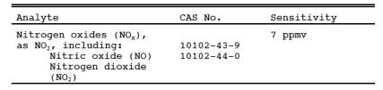
1.1 Analytes.
1.2 Applicability.
This method applies
to the measurement of NOx
emissions from fossil-fuel fired
steam generators, electric utility plants, nitric acid plants, or other sources
as specified in the regulations.
1.3 Data Quality Objectives.
Adherence to the
requirements of this method will enhance the quality of the data obtained from
air pollutant sampling methods.
2.0 Summary of Method.
An integrated gas
sample is extracted from the stack and passed through impingers containing an
alkaline potassium permanganate solution; NOx (NO + NO2) emissions are oxidized to NO2 - and NO3 -. Then NO3- is
reduced to NO2-with cadmium, and the NO2- is analyzed colorimetrically.
3.0 Definitions. [Reserved]
4.0 Interferences.
Possible interferents
are sulfur dioxides (S02) and ammonia (NH3).
4.1 High
concentrations of SO2
could interfere because SO2 consumes MnO4-
(as does NOx) and, therefore, could reduce the NOx collection
efficiency. However, when sampling emissions from a coal-fired electric utility
plant burning 2.1 percent sulfur coal with no control of SO2 emissions, collection efficiency was not reduced. In fact,
calculations show that sampling 3000 ppm SO2 will
reduce the MnO4- concentration by only 5 percent if all the SO2 is consumed in the first impinger.
4.2 Ammonia (NH3) is slowly oxidized to NO3- by the
absorbing solution. At 100 ppm NH3 in the
gas stream, an interference of 6 ppm NOx (11 mg NO2/m3) was observed when the sample was analyzed 10
days after collection. Therefore, the method may not be applicable to plants
using NH3 injection to control NOx emissions unless means are taken to correct the results. An
equation has been developed to allow quantification of the interference and is
discussed in Reference 5 of Section 16.0.
5.0 Safety.
5.1 Disclaimer.
This method may
involve hazardous materials, operations, and equipment. This test method may
not address all of the safety problems associated with its use. It is the
responsibility of the user of this test method to establish appropriate safety
and health practices and to determine the applicability of regulatory
limitations prior to performing this test method.
5.2 Corrosive Reagents.
The following
reagents are hazardous. Personal protective equipment and safe procedures are
useful in preventing chemical splashes. If contact occurs, immediately flush
with copious amounts of water for at least 15 minutes. Remove clothing under
shower and decontaminate. Treat residual chemical burns as thermal burns.
5.2.1 Hydrochloric Acid (HCl). Highly toxic and corrosive. Causes severe damage to skin. Vapors
are highly irritating to eyes, skin, nose, and lungs, causing severe damage.
May cause bronchitis, pneumonia, or edema of lungs. Exposure to vapor
concentrations of 0.13 to 0.2 percent can be lethal in minutes. Will react with
metals, producing hydrogen.
5.2.2 Oxalic Acid (COOH)2.
Poisonous. Irritating to eyes, skin, nose,
and throat.
5.2.3 Sodium Hydroxide (NaOH). Causes severe damage to eye tissues and to skin. Inhalation causes
irritation to nose, throat, and lungs. Reacts exothermically with small amounts
of water.
5.2.4 Potassium Permanganate (KMnO4). Caustic, strong
oxidizer. Avoid bodily contact with.
6.0 Equipment and Supplies.
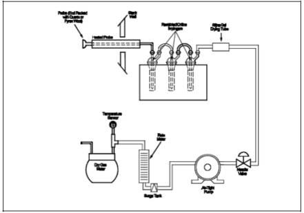
6.1 Sample Collection and Sample Recovery.
A schematic of the
Method 7C sampling train is shown in Figure 7C-1, and
component parts are discussed below. Alternative apparatus and procedures are
allowed provided acceptable accuracy and precision can be demonstrated to the
satisfaction of the Administrator.
6.1.1 Probe. Borosilicate
glass tubing, sufficiently heated to prevent water condensation and equipped
with an in-stack or heated out-of-stack filter to remove particulate matter (a
plug of glass wool is satisfactory for this purpose). Stainless steel or Teflon
tubing may also be used for the probe.
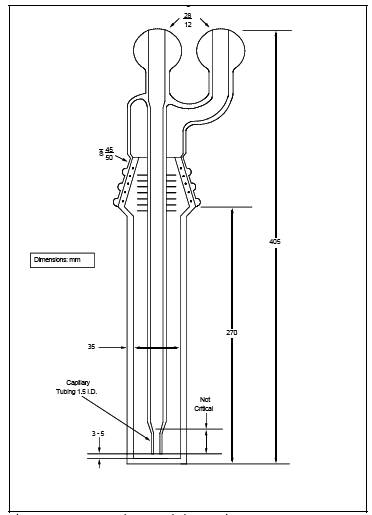
6.1.2 Impingers. Three
restricted-orifice glass impingers, having the specifications given in Figure 7C-2, are required for each sampling train. The
impingers must be connected in series with leak-free glass connectors. Stopcock
grease may be used, if necessary, to prevent leakage. (The impingers can be
fabricated by a glass blower if not available commercially.)
6.1.3 Glass Wool, Stopcock Grease, Drying Tube, Valve, Pump,
Barometer, and Vacuum Gauge and Rotameter. Same
as in Method 6, Sections 6.1.1.3, 6.1.1.4, 6.1.1.6, 6.1.1.7, 6.1.1.8, 6.1.2,
and 6.1.3, respectively.
6.1.4 Rate Meter. Rotameter,
or equivalent, accurate to within 2 percent at the selected flow rate of
between 400 and 500 ml/min (0.014 to 0.018 cfm). For rotameters, a range of 0
to 1 liter/min (0 to 0.035 cfm) is recommended.
6.1.5 Volume Meter.
Dry gas meter (DGM)
capable of measuring the sample volume under the sampling conditions of 400 to
500 ml/min (0.014 to 0.018 cfm) for 60 minutes within an accuracy of 2 percent.
6.1.6 Filter. To remove NOx from ambient air, prepared by adding 20 g of 5-angstrom molecular sieve to a cylindrical tube (e.g., a polyethylene drying tube).
6.1.7 Polyethylene Bottles. 1-liter,
for sample recovery.
6.1.8 Funnel and Stirring Rods. For sample recovery.
6.2 Sample Preparation and Analysis.
6.2.1 Hot Plate. Stirring
type with 50- by 10-mm Teflon-coated stirring bars.
6.2.2 Beakers. 400-,
600-, and 1000-ml capacities.
6.2.3 Filtering Flask. 500-ml
capacity with side arm.
6.2.4 Buchner Funnel. 75-mm
ID, with spout equipped with a 13-mm ID by 90-mm long piece of Teflon tubing to
minimize possibility of aspirating sample solution during filtration.
6.2.5 Filter Paper. Whatman
GF/C, 7.0-cm diameter.
6.2.6 Stirring Rods.
6.2.7 Volumetric Flasks. 100-,
200- or 250-, 500-, and 1000-ml capacity.
6.2.8 Watch Glasses. To
cover 600- and 1000-ml beakers.
6.2.9 Graduated Cylinders. 50-
and 250-ml capacities.
6.2.10 Pipettes. Class
A.
6.2.11 pH Meter. To
measure pH from 0.5 to 12.0.
6.2.12 Burette. 50-ml with
a micrometer type stopcock. (The stopcock is Catalog No. 8225-t-05, Ace Glass,
Inc., Post Office Box 996, Louisville, Kentucky 50201.) Place a glass wool plug
in bottom of burette. Cut off burette at a height of 43 cm (17 in.) from the
top of plug, and have a blower attach a glass funnel to top of burette such
that the diameter of the burette remains essentially unchanged. Other means of
attaching the funnel are acceptable.
6.2.13 Glass Funnel. 75-mm
ID at the top.
6.2.14 Spectrophotometer. Capable
of measuring absorbance at 540 nm; 1-cm cells are adequate.
6.2.15 Metal Thermometers. Bimetallic
thermometers, range 0 to 150 ˚C (32 to 300 ˚F).
6.2.16 Culture Tubes. 20-
by 150-mm, Kimax No. 45048.
6.2.17 Parafilm "M." Obtained from American Can Company, Greenwich, Connecticut 06830.
6.2.18 CO2 Measurement
Equipment. Same as in Method 3, Section 6.0.
7.0 Reagents and Standards.
Unless otherwise
indicated, it is intended that all reagents conform to the specifications
established by the Committee on Analytical Reagents of the American Chemical
Society, where such specifications are available; otherwise, use the best
available grade.
7.1 Sample Collection.
7.1.1 Water.
Deionized distilled to conform to ASTM Specification D 1193-77 or 91 Type 3
(incorporated by reference - see §60.17).
7.1.2 Potassium
Permanganate, 4.0 Percent (w/w), Sodium Hydroxide, 2.0 Percent (w/w) solution
(KMnO4/NaOH solution). Dissolve 40.0 g of KMnO4 and 20.0 g of NaOH in 940 ml of water.
7.2 Sample Preparation and Analysis.
7.2.1 Water. Same as
in Section 7.1.1.
7.2.2 Oxalic Acid Solution.
Dissolve 48 g of oxalic acid [(COOH)2·2H2O] in water, and dilute to 500 ml. Do not heat the solution.
7.2.3 Sodium
Hydroxide, 0.5 N. Dissolve 20 g of NaOH in water, and dilute to 1 liter.
7.2.4 Sodium
Hydroxide, 10 N. Dissolve 40 g of NaOH in water, and dilute to 100 ml.
7.2.5 Ethylenediamine
Tetraacetic Acid (EDTA) Solution, 6.5 percent (w/v). Dissolve 6.5 g of EDTA
(disodium salt) in water, and dilute to 100 ml. Dissolution is best
accomplished by using a magnetic stirrer.
7.2.6 Column Rinse
Solution. Add 20 ml of 6.5 percent EDTA solution to 960 ml of water, and adjust
the pH to between 11.7 and 12.0 with 0.5 N NaOH.
7.2.7 Hydrochloric
Acid (HCl), 2 N. Add 86 ml of concentrated HCl to a 500 ml-volumetric flask
containing water, dilute to volume, and mix well. Store in a glass-stoppered
bottle.
7.2.8 Sulfanilamide
Solution. Add 20 g of sulfanilamide [melting point 165 to 167 ˚C (329 to 333
˚F)] to 700 ml of water. Add, with mixing, 50 ml concentrated phosphoric acid
(85 percent), and dilute to 1000 ml. This solution is stable for at least 1
month, if refrigerated.
7.2.9
N-(1-Naphthyl)-Ethylenediamine Dihydrochloride (NEDA) Solution. Dissolve 0.5 g
of NEDA in 500 ml of water. An aqueous solution should have one absorption peak
at 320 nm over the range of 260 to 400 nm. NEDA that shows more than one
absorption peak over this range is impure and should not be used. This solution
is stable for at least 1 month if protected from light and refrigerated.
7.2.10 Cadmium.
Obtained from Matheson Coleman and Bell, 2909 Highland Avenue, Norwood, Ohio
45212, as EM Laboratories Catalog No. 2001. Prepare by rinsing in 2 N HCl for 5
minutes until the color is silver-grey. Then rinse the cadmium with water until
the rinsings are neutral when tested with pH paper. CAUTION: H2 is liberated during preparation. Prepare in an exhaust hood away
from any flame or combustion source.
7.2.11
Sodium Sulfite (NaNO2) Standard Solution, Nominal Concentration, 1000
µg NO2-/ml. Desiccate NaNO2 overnight. Accurately weigh 1.4 to 1.6 g of NaNO2 (assay of 97 percent NaNO2 or
greater), dissolve in water, and dilute to 1 liter. Calculate the exact NO2- concentration using Equation 7C-1 in Section 12.2. This solution is stable for at least 6
months under laboratory conditions.
7.2.12 Potassium
Nitrate (KNO3) Standard Solution. Dry KNO3 at 110 ˚C (230 ˚F) for 2 hours, and cool in a desiccator.
Accurately weigh 9 to 10 g of KNO3 to within
0.1 mg, dissolve in water, and dilute to 1 liter. Calculate the exact NO3- concentration using Equation 7C-2 in Section 12.3. This solution is stable for 2 months
without preservative under laboratory conditions.
7.2.13 Spiking
Solution. Pipette 7 ml of the KNO3 standard
into a 100-ml volumetric flask, and dilute to volume.
7.2.14 Blank
Solution. Dissolve 2.4 g of KMnO4 and 1.2 g of NaOH in
96 ml of water. Alternatively, dilute 60 ml of KMnO4/NaOH solution to 100 ml.
7.2.15 Quality
Assurance Audit Samples. Same as in Method 7,
Section 7.3.10. When requesting audit samples, specify that they be in the
appropriate concentration range for Method 7C.
8.0 Sample Collection, Preservation, Storage, and Transport.
8.1 Preparation of Sampling Train.
Add 200 ml of KMnO4/NaOH solution (Section 7.1.2) to each of three impingers, and
assemble the train as shown in Figure 7C-1. Adjust the probe heater to a
temperature sufficient to prevent water condensation.
8.2 Leak-Checks.
Same as in Method 6, Section 8.2.
8.3 Sample Collection.
8.3.1 Record the
initial DGM reading and barometric pressure. Determine the sampling point or
points according to the appropriate regulations (e.g., § 60.46(b)(5) of 40 CFR Part 60). Position the
tip of the probe at the sampling point, connect the probe to the first
impinger, and start the pump. Adjust the sample flow to a value between 400 and
500 ml/min (0.014 and 0.018 cfm). CAUTION: DO NOT EXCEED THESE FLOW RATES. Once
adjusted, maintain a constant flow rate during the entire sampling run. Sample
for 60 minutes. For relative accuracy (RA) testing of continuous emission
monitors, the minimum sampling time is 1 hour, sampling 20 minutes at each
traverse point.
NOTE: When the SO2 concentration
is greater than 1200 ppm, the sampling time may have to be reduced to 30
minutes to eliminate plugging of the impinger orifice with MnO2. For RA tests with SO2 greater
than 1200 ppm, sample for 30 minutes (10 minutes at each point).
8.3.2 Record the DGM
temperature, and check the flow rate at least every 5 minutes. At the
conclusion of each run, turn off the pump, remove the probe from the stack, and
record the final readings. Divide the sample volume by the sampling time to
determine the average flow rate. Conduct the mandatory post-test leak-check. If
a leak is found, void the test run, or use procedures acceptable to the
Administrator to adjust the sample volume for the leakage.
8.4 CO2 Measurement.
During sampling,
measure the CO2 content of the stack gas near the sampling point
using Method 3. The single-point grab sampling procedure is adequate, provided
the measurements are made at least three times (near the start, midway, and
before the end of a run), and the average CO2 concentration
is computed. The Orsat or Fyrite analyzer may be used for this analysis.
8.5 Sample Recovery.
Disconnect the
impingers. Pour the contents of the impingers into a 1-liter polyethylene
bottle using a funnel and a stirring rod (or other means) to prevent spillage.
Complete the quantitative transfer by rinsing the impingers and connecting
tubes with water until the rinsings are clear to light pink, and add the
rinsings to the bottle. Mix the sample, and mark the solution level. Seal and
identify the sample container.
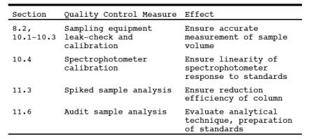
9.0 Quality Control.
10.0 Calibration and Standardizations.
10.1 Volume Metering
System. Same as Method 6, Section 10.1. For
detailed instructions on carrying out these calibrations, it is suggested that
Section 3.5.2 of Reference 4 of Section 16.0 be consulted.
10.2 Temperature
Sensors and Barometer. Same as in Method 6, Sections 10.2 and 10.4,
respectively.
10.3 Check of Rate
Meter Calibration Accuracy (Optional). Disconnect the probe from the first
impinger, and connect the filter. Start the pump, and adjust the rate meter to
read between 400 and 500 ml/min (0.014 and 0.018 cfm). After the flow rate has
stabilized, start measuring the volume sampled, as recorded by the dry gas
meter and the sampling time. Collect enough volume to measure accurately the
flow rate. Then calculate the flow rate. This average flow rate must be less
than 500 ml/min (0.018 cfm) for the sample to be valid; therefore, it is
recommended that the flow rate be checked as above prior to each test.
10.4
Spectrophotometer.
10.4.1 Dilute 5.0 ml
of the NaNO2 standard solution to 200 ml with water. This
solution nominally contains 25 µg NO2 -/ml. Use
this solution to prepare calibration standards to cover the range of 0.25 to
3.00 µg NO2-/ml. Prepare a minimum of three standards each
for the linear and slightly nonlinear (described below) range of the curve. Use
pipettes for all additions.
10.4.2 Measure the
absorbance of the standards and a water blank as instructed in Section 11.5.
Plot the net absorbance vs. µg NO2-/ml. Draw
a smooth curve through the points. The curve should be linear up to an
absorbance of approximately 1.2 with a slope of approximately 0.53 absorbance
units/µg NO2-/ml. The curve should pass through the origin.
The curve is slightly nonlinear from an absorbance of 1.2 to 1.6.
11.0 Analytical Procedures.
11.1 Sample
Stability.
Collected samples are
stable for at least four weeks; thus, analysis must occur within 4 weeks of
collection.
11.2 Sample
Preparation.
11.2.1 Prepare a
cadmium reduction column as follows: Fill the burette with water. Add freshly
prepared cadmium slowly, with tapping, until no further settling occurs. The
height of the cadmium column should be 39 cm (15 in). When not in use, store
the column under rinse solution.
NOTE: The column should not contain any bands of
cadmium fines. This may occur if regenerated cadmium is used and will greatly
reduce the column lifetime.
11.2.2 Note the level
of liquid in the sample container, and determine whether any sample was lost
during shipment. If a noticeable amount of leakage has occurred, the volume
lost can be determined from the difference between initial and final solution
levels, and this value can then be used to correct the analytical result.
Quantitatively transfer the contents to a 1-liter volumetric flask, and dilute
to volume.
11.2.3 Take a 100-ml
aliquot of the sample and blank (unexposed KMnO4/NaOH)
solutions, and transfer to 400-ml beakers containing magnetic stirring bars.
Using a pH meter, add concentrated H2SO4 with stirring until a pH of 0.7 is obtained. Allow the solutions to
stand for 15 minutes. Cover the beakers with watch glasses, and bring the
temperature of the solutions to 50 ˚C (122 ˚F). Keep the temperature below 60
˚C (140 ˚F). Dissolve 4.8 g of oxalic acid in a minimum volume of water,
approximately 50 ml, at room temperature. Do not heat the solution. Add this
solution slowly, in increments, until the KMnO4 solution
becomes colorless. If the color is not completely removed, prepare some more of
the above oxalic acid solution, and add until a colorless solution is obtained.
Add an excess of oxalic acid by dissolving 1.6 g of oxalic acid in 50 ml of
water, and add 6 ml of this solution to the colorless solution. If suspended
matter is present, add concentrated H2SO4 until a clear solution is obtained.
11.2.4 Allow the
samples to cool to near room temperature, being sure that the samples are still
clear. Adjust the pH to between 11.7 and 12.0 with 10 N NaOH. Quantitatively
transfer the mixture to a Buchner funnel containing GF/C filter paper, and
filter the precipitate. Filter the mixture into a 500-ml filtering flask. Wash
the solid material four times with water. When filtration is complete, wash the
Teflon tubing, quantitatively transfer the filtrate to a 500-ml volumetric
flask, and dilute to volume. The samples are now ready for cadmium reduction.
Pipette a 50-ml aliquot of the sample into a 150-ml beaker, and add a magnetic
stirring bar. Pipette in 1.0 ml of 6.5 percent EDTA solution, and mix.
11.3 Determine the
correct stopcock setting to establish a flow rate of 7 to 9 ml/min of column
rinse solution through the cadmium reduction column. Use a 50-ml graduated
cylinder to collect and measure the solution volume. After the last of the
rinse solution has passed from the funnel into the burette, but before air
entrapment can occur, start adding the sample, and collect it in a 250-ml graduated
cylinder. Complete the quantitative transfer of the sample to the column as the
sample passes through the column. After the last of the sample has passed from
the funnel into the burette, start adding 60 ml of column rinse solution, and
collect the rinse solution until the solution just disappears from the funnel.
Quantitatively transfer the sample to a 200-ml volumetric flask (a 250-ml flask
may be required), and dilute to volume. The samples are now ready for NO2- analysis.
NOTE: Two spiked samples should be run with every
group of samples passed through the column. To do this, prepare two additional
50-ml aliquots of the sample suspected to have the highest NO2- concentration, and add 1 ml of the spiking
solution to these aliquots. If the spike recovery or column efficiency (see
Section 12.2) is below 95 percent, prepare a new column, and repeat the cadmium
reduction.
11.4 Repeat the
procedures outlined in Sections 11.2 and 11.3 for each sample and each blank.
11.5 Sample Analysis.
Pipette 10 ml of sample into a culture tube. Pipette in 10 ml of sulfanilamide
solution and 1.4 ml of NEDA solution. Cover the culture tube with parafilm, and
mix the solution. Prepare a blank in the same manner using the sample from
treatment of the unexposed KMnO4/NaOH solution. Also,
prepare a calibration standard to check the slope of the calibration curve.
After a 10-minute color development interval, measure the absorbance at 540 nm
against water. Read µg NO2-/ml from the calibration curve. If the absorbance
is greater than that of the highest calibration standard, use less than 10 ml
of sample, and repeat the analysis. Determine the NO2- concentration using the calibration curve
obtained in Section 10.4.
NOTE: Some test tubes give a high blank NO2- value but culture tubes do not.
11.6 Audit Sample
Analysis. Same as in Method 7, Section 11.4.
12.0 Data Analysis and Calculations.
Carry out
calculations, retaining at least one extra significant figure beyond that of
the acquired data. Round off figures after final calculation.
12.1 Nomenclature.
B = Analysis of
blank, µg NO2-/ml.
C = Concentration of
NOx as NO2, dry
basis, mg/dsm3.
E = Column
efficiency, dimensionless
K2 = 10-3 mg/µg.
m = Mass of NOx, as NO2, in sample, µg.
Pbar = Barometric pressure, mm Hg (in. Hg).
Pstd = Standard absolute pressure, 760 mm Hg (29.92
in. Hg).
s = Concentration of
spiking solution, µg NO3/ml.
S = Analysis of
sample, µg NO2-/ml.
Tm = Average dry gas meter absolute temperature, ˚K.
Tstd = Standard absolute temperature, 293 ˚K (528
˚R).
Vm(std) = Dry gas volume measured by the dry gas meter,
corrected to standard conditions, dscm (dscf).
Vm = Dry gas volume as measured by the dry gas meter, scm (scf).
x = Analysis of
spiked sample, µg NO2-/ml.
X = Correction factor
for CO2 collection
= 100/[100 - %CO2(V/V)].
y = Analysis of
unspiked sample, µg NO2-/ml.
Y = Dry gas meter
calibration factor.
1.0 ppm NO = 1.247 mg
NO/m3 at STP.
1.0 ppm NO2 = 1.912 mg NO2/m3 at STP.
1 ft3 = 2.832 x 10⁻²
m3.
12.2
NO2 Concentration. Calculate the NO2concentration of the solution (see Section
7.2.11) using the following equation:
![]()
12.3 NO3 Concentration. Calculate the NO3 concentration
of the KNO3 solution (see Section 7.2.12) using the
following equation:
![]()
12.4 Sample Volume,
Dry Basis, Corrected to Standard Conditions.
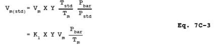
where:
K1 = 0.3855 ˚K/mm Hg for metric units.
= 17.65 ˚R/in. Hg for
English units.
12.5 Efficiency of
Cadmium Reduction Column. Calculate this value as follows:
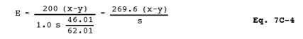
where:
200 = Final volume of
sample and blank after passing through the column, ml.
1.0 = Volume of
spiking solution added, ml.
46.01 = µg NO2-/µmole.
62.01 = µg NO3-/µmole.
12.6 Total µg NO2.
![]()
where:
500 = Total volume of
prepared sample, ml.
50 = Aliquot of
prepared sample processed through cadmium column, ml.
100 = Aliquot of KMnO4/NaOH solution, ml.
1000 = Total volume
of KMnO4/NaOH solution, ml.
12.7 Sample
Concentration.
![]()
13.0 Method Performance.
13.1 Precision. The
intra-laboratory relative standard deviation for a single measurement is 2.8
and 2.9 percent at 201 and 268 ppm NOx,
respectively.
13.2 Bias. The method
does not exhibit any bias relative to Method 7.
13.3 Range. The lower
detectable limit is 13 mg NOx/m3, as NO2
(7 ppm NOx) when sampling at 500 ml/min for 1 hour. No upper limit has been
established; however, when using the recommended sampling conditions, the
method has been found to collect NOx emissions
quantitatively up to 1782 mg NOx/m3, as NO2
(932 ppm NOx).
14.0 Pollution Prevention. [Reserved]
15.0 Waste Management. [Reserved]
16.0 References.
1. Margeson, J.H., W.J.
Mitchell, J.C. Suggs, and M.R. Midgett. Integrated Sampling and Analysis
Methods for Determining NOx
Emissions at Electric Utility
Plants. U.S. Environmental Protection Agency, Research Triangle Park, NC.
Journal of the Air Pollution Control Association. 32:1210-1215. 1982.
2. Memorandum and
attachment from J.H. Margeson, Source Branch, Quality Assurance Division,
Environmental Monitoring Systems Laboratory, to The Record, EPA. March 30,
1983. NH3 Interference in Methods 7C and 7D.
3. Margeson, J.H.,
J.C. Suggs, and M.R. Midgett. Reduction of Nitrate to Nitrite with Cadmium.
Anal. Chem. 52:1955-57. 1980.
4. Quality Assurance
Handbook for Air Pollution Measurement Systems. Volume III - Stationary Source
Specific Methods. U.S. Environmental Protection Agency. Research Triangle Park,
NC. Publication No. EPA-600/4-77-027b. August 1977.
5. Margeson, J.H., et
al. An Integrated Method for Determining NOx Emissions
at Nitric Acid Plants. Analytical Chemistry. 47 (11):1801. 1975.
17.0 Tables, Diagrams, Flowcharts, and Validation Data.
Figure
7C-1. NOx Sampling Train.
Figure
7C-2. Restricted-Orifice Impinger.