METHOD
7 - DETERMINATION OF NITROGEN OXIDE EMISSIONS FROM STATIONARY SOURCES.
NOTE: This method does not include all of the
specifications (e.g.,
equipment and supplies) and procedures (e.g., sampling and analytical) essential to its
performance. Some material is incorporated by reference from other methods in
this part. Therefore, to obtain reliable results, persons using this method
should have a thorough knowledge of at least the following additional test
methods: Method 1 and Method
5.
5.2.1 Hydrogen Peroxide
(H2O2).
5.2.3 Sodium Hydroxide
(NaOH).
6.1.9 Volumetric
Pipette. 25-ml.
6.1.10 Stopcock and
Ground Joint Grease.
6.2.5 Test Paper for
Indicating pH.
6.3.2 Porcelain
Evaporating Dishes.
6.3.4 Dropping Pipette
or Dropper.
6.3.10 Test Paper for
Indicating pH.
7.3.5 Potassium Nitrate
(KNO3).
7.3.7 Working Standard
KNO3 Solution.
7.3.8 Phenoldisulfonic
Acid Solution.
7.3.9 Concentrated
Ammonium Hydroxide.
7.3.10 Quality
Assurance Audit Samples.
8.0 Sample Collection,
Preservation, Storage and Transport.
10.0 Calibration and
Standardization.
12.0 Data Analysis and
Calculations.
12.2 Spectrophotometer
Calibration Factor.
12.3 Sample Volume, Dry
Basis, Corrected to Standard Conditions.
12.5 Sample
Concentration, Dry Basis, Corrected to Standard Conditions.
12.6 Relative Error for
QA Audit Samples.
14.0 Pollution
Prevention. [Reserved]
15.0 Waste Management.
[Reserved]
17.0 Tables, Diagrams,
Flowcharts, and Validation Data.
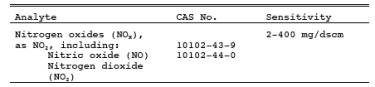
1.0 Scope and Application.
1.1 Analytes.
1.2 Applicability.
This method is
applicable for the measurement of nitrogen oxides (NOx) emitted from stationary sources.
1.3 Data Quality Objectives.
Adherence to the
requirements of this method will enhance the quality of the data obtained from
air pollutant sample methods.
2.0 Summary of Method.
A grab sample is
collected in an evacuated flask containing a dilute sulfuric acid-hydrogen
peroxide absorbing solution, and the nitrogen oxides, except nitrous oxide, are
measured colorimetrically using the phenoldisulfonic acid (PDS) procedure.
3.0 Definitions. [Reserved]
4.0 Interferences.
Biased results have been
observed when sampling under conditions of high sulfur dioxide concentrations
(above 2000 ppm).
5.0 Safety.
5.1 Disclaimer.
This method may
involve hazardous materials, operations, and equipment. This test method may
not address all of the safety problems associated with its use. It is the
responsibility of the user to establish appropriate safety and health practices
and to determine the applicability of regulatory limitations prior to
performing this test method.
5.2 Corrosive Reagents.
The following
reagents are hazardous. Personal protective equipment and safe procedures are
useful in preventing chemical splashes. If contact occurs, immediately flush
with copious amounts of water for at least 15 minutes. Remove clothing under
shower and decontaminate. Treat residual chemical burns as thermal burns.
5.2.1 Hydrogen Peroxide (H2O2).
Irritating to eyes,
skin, nose, and lungs.
5.2.2 Phenoldisulfonic Acid.
Irritating to eyes
and skin.
5.2.3 Sodium Hydroxide (NaOH).
Causes severe damage
to eyes and skin. Inhalation causes irritation to nose, throat, and lungs.
Reacts exothermically with limited amounts of water.
5.2.4 Sulfuric Acid (H2SO4).
Rapidly destructive
to body tissue. Will cause third degree burns. Eye damage may result in
blindness. Inhalation may be fatal from spasm of the larynx, usually within 30
minutes. May cause lung tissue damage with edema. 1 mg/m3 for 8 hours will cause lung damage or, in higher concentrations,
death. Provide ventilation to limit inhalation. Reacts violently with metals
and organics.
5.2.5 Phenol.
Poisonous and
caustic. Do not handle with bare hands as it is absorbed through the skin.
6.0 Equipment and Supplies.
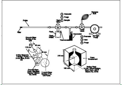
6.1 Sample Collection.
A schematic of the sampling
train used in performing this method is shown in Figure
7-1. Other grab sampling systems or equipment, capable of measuring sample
volume to within 2.0 percent and collecting a sufficient sample volume to allow
analytical reproducibility to within 5 percent, will be considered acceptable
alternatives, subject to the approval of the Administrator. The following items
are required for sample
collection:
6.1.1 Probe.
Borosilicate glass
tubing, sufficiently heated to prevent water condensation and equipped with an
in-stack or heated out-of-stack filter to remove particulate matter (a plug of
glass wool is satisfactory for this purpose). Stainless steel or Teflon tubing
may also be used for the probe. Heating is not necessary if the probe remains
dry during the purging period.
6.1.2 Collection Flask.
Two-liter
borosilicate, round bottom flask, with short neck and 24/40 standard taper
opening, protected against implosion or breakage.
6.1.3 Flask Valve.
T-bore stopcock
connected to a 24/40 standard taper joint.
6.1.4 Temperature Gauge.
Dial-type
thermometer, or other temperature gauge, capable of measuring 1 °C (2 °F)
intervals from -5 to 50 °C (23 to 122 °F).
6.1.5 Vacuum Line.
Tubing capable of withstanding
a vacuum of 75 mm (3 in.) Hg absolute pressure, with "T" connection
and T-bore stopcock.
6.1.6 Vacuum Gauge.
U-tube manometer, 1
meter (39 in.), with 1 mm (0.04 in.) divisions, or other gauge capable of
measuring pressure to within 2.5 mm (0.10 in.) Hg.
6.1.7 Pump.
Capable of evacuating
the collection flask to a pressure equal to or less than 75 mm (3 in.) Hg
absolute.
6.1.8 Squeeze Bulb.
One-way.
6.1.9 Volumetric Pipette. 25-ml.
6.1.10 Stopcock and Ground Joint Grease.
A highvacuum, high-temperature
chlorofluorocarbon grease is required. Halocarbon 25-5S has been found to be
effective.
6.1.11 Barometer.
Mercury, aneroid, or
other barometer capable of measuring atmospheric pressure to within 2.5 mm (0.1
in.) Hg. See NOTE in Method 5, Section 6.1.2.
6.2 Sample Recovery.
The following items
are required for sample recovery:
6.2.1 Graduated Cylinder.
50-ml with 1 ml
divisions.
6.2.2 Storage Containers.
Leak-free
polyethylene bottles.
6.2.3 Wash Bottle.
Polyethylene or
glass.
6.2.4 Glass Stirring Rod.
6.2.5 Test Paper for Indicating pH.
To cover the pH range
of 7 to 14.
6.3 Analysis.
The following items
are required for analysis:
6.3.1 Volumetric Pipettes.
Two 1-ml, two 2-ml,
one 3-ml, one 4-ml, two 10-ml, and one 25-ml for each sample and standard.
6.3.2 Porcelain Evaporating Dishes.
175- to 250-ml
capacity with lip for pouring, one for each sample and each standard. The Coors
No. 45006 (shallowform, 195-ml) has been found to be satisfactory.
Alternatively, polymethyl pentene beakers (Nalge No. 1203, 150-ml), or glass
beakers (150-ml) may be used. When glass beakers are used, etching of the
beakers may cause solid matter to be present in the analytical step; the solids
should be removed by filtration.
6.3.3 Steam Bath.
Low-temperature ovens
or thermostatically controlled hot plates kept below 70 °C (160 °F) are
acceptable alternatives.
6.3.4 Dropping Pipette or Dropper.
Three required.
6.3.5 Polyethylene Policeman.
One for each sample
and each standard.
6.3.6 Graduated Cylinder.
100-ml with 1-ml
divisions.
6.3.7 Volumetric Flasks.
50-ml (one for each
sample and each standard), 100-ml (one for each sample and each standard, and
one for the working standard KNO3 solution), and
1000-ml (one).
6.3.8 Spectrophotometer.
To measure at 410 nm.
6.3.9 Graduated Pipette.
10-ml with 0.1-ml
divisions.
6.3.10 Test Paper for Indicating pH.
To cover the pH range
of 7 to 14.
6.3.11 Analytical Balance.
To measure to within
0.1 mg.
7.0 Reagents and Standards.
Unless otherwise
indicated, it is intended that all reagents conform to the specifications
established by the Committee on Analytical Reagents of the American Chemical
Society, where such specifications are available; otherwise, use the best
available grade.
7.1 Sample Collection.
The following
reagents are required for sampling:
7.1.1 Water.
Deionized distilled
to conform to ASTM D 1193-77 or 91 Type 3 (incorporated by reference - see
§60.17). The KMnO4 test for oxidizable organic matter may be
omitted when high concentrations of organic matter are not expected to be
present.
7.1.2 Absorbing Solution.
Cautiously add 2.8 ml
concentrated H2SO4 to a
1-liter flask partially filled with water. Mix well, and add 6 ml of 3 percent
hydrogen peroxide, freshly prepared from 30 percent hydrogen peroxide solution.
Dilute to 1 liter of water and mix well. The absorbing solution should be used
within 1 week of its preparation. Do not expose to extreme heat or direct sunlight.
7.2 Sample Recovery.
The following
reagents are required for sample recovery:
7.2.1 Water.
Same as in 7.1.1.
7.2.2 Sodium Hydroxide
1 N. Dissolve 40 g
NaOH in water, and dilute to 1 liter.
7.3 Analysis.
The following
reagents and standards are required for analysis:
7.3.1 Water.
Same as in 7.1.1.
7.3.2 Fuming Sulfuric Acid.
15 to 18 percent by
weight free sulfur trioxide. HANDLE WITH CAUTION.
7.3.3 Phenol.
White solid.
7.3.4 Sulfuric Acid.
Concentrated, 95
percent minimum assay.
7.3.5 Potassium Nitrate (KNO3).
Dried at 105 to 110
°C (221 to 230 °F) for a minimum of 2 hours just prior to preparation of
standard solution.
7.3.6 Standard KNO3 Solution.
Dissolve exactly
2.198 g of dried KNO3
in water, and dilute to 1 liter
with water in a 1000-ml volumetric flask.
7.3.7 Working Standard KNO3 Solution.
Dilute 10 ml of the
standard solution to 100 ml with water. One ml of the working standard solution
is equivalent to 100 µg nitrogen dioxide (NO2).
7.3.8 Phenoldisulfonic Acid Solution.
Dissolve 25 g of pure
white phenol solid in 150 ml concentrated sulfuric acid on a steam bath. Cool,
add 75 ml fuming sulfuric acid (15 to 18 percent by weight free sulfur trioxide
- HANDLE WITH CAUTION), and heat at 100 °C (212 °F) for 2 hours. Store in a
dark, stoppered bottle.
7.3.9 Concentrated Ammonium Hydroxide.
7.3.10 Quality Assurance Audit Samples.
When making
compliance determinations, and upon availability, audit samples may be obtained
from the appropriate EPA Regional Office or from the responsible enforcement
authority. NOTE: The responsible enforcement authority should be
notified at least 30 days prior to the test date to allow sufficient time for
sample delivery.
8.0 Sample Collection, Preservation, Storage and Transport.
8.1 Sample Collection.
8.1.1 Flask Volume.
The volume of the
collection flask and flask valve combination must be known prior to sampling.
Assemble the flask and flask valve, and fill with water to the stopcock.
Measure the volume of water to ± 10 ml. Record this volume on the flask.
8.1.2 Pipette 25 ml
of absorbing solution into a sample flask, retaining a sufficient quantity for
use in preparing the calibration standards. Insert the flask valve stopper into
the flask with the valve in the "purge" position. Assemble the
sampling train as shown in Figure 7-1, and place the
probe at the sampling point. Make sure that all fittings are tight and
leak-free, and that all ground glass joints have been greased properly with a
high-vacuum, high- temperature chlorofluorocarbon-based stopcock grease. Turn
the flask valve and the pump valve to their "evacuate" positions.
Evacuate the flask to 75 mm (3 in.) Hg absolute pressure, or less. Evacuation
to a pressure approaching the vapor pressure of water at the existing
temperature is desirable. Turn the pump valve to its "vent" position,
and turn off the pump. Check for leakage by observing the manometer for any
pressure fluctuation. (Any variation greater than 10 mm (0.4 in.) Hg over a
period of 1 minute is not acceptable, and the flask is not to be used until the
leakage problem is corrected. Pressure in the flask is not to exceed 75 mm (3
in.) Hg absolute at the time sampling is commenced.) Record the volume of the
flask and valve (Vf), the flask temperature (Ti), and the barometric pressure. Turn the flask valve
counterclockwise to its "purge" position, and do the same with the
pump valve. Purge the probe and
the vacuum tube using the squeeze bulb. If condensation occurs in the probe and
the flask valve area, heat the probe, and purge until the condensation
disappears. Next, turn the pump valve to its "vent" position. Turn
the flask valve clockwise to its "evacuate" position, and record the
difference in the mercury levels in the manometer. The absolute internal
pressure in the flask (Pi) is equal to the barometric pressure less the
manometer reading. Immediately turn the flask valve to the "sample"
position, and permit the gas to enter the flask until pressures in the flask
and sample line (i.e., duct,
stack) are equal. This will usually require about 15 seconds; a longer period
indicates a plug in the probe, which must be corrected before sampling is
continued. After collecting the sample, turn the flask valve to its
"purge" position, and disconnect the flask from the sampling train.
8.1.3 Shake the flask
for at least 5 minutes.
8.1.4 If the gas
being sampled contains insufficient oxygen for the conversion of NO to NO2 (e.g., an
applicable subpart of the standards may require taking a sample of a
calibration gas mixture of NO in N2), then
introduce oxygen into the flask to permit this conversion. Oxygen may be
introduced into the flask by one of three methods: (1) Before evacuating the
sampling flask, flush with pure cylinder oxygen, then evacuate flask to 75 mm
(3 in.) Hg absolute pressure or less; or (2) inject oxygen into the flask after
sampling; or (3) terminate sampling with a minimum of 50 mm (2 in.) Hg vacuum
remaining in the flask, record this final pressure, and then vent the flask to
the atmosphere until the flask pressure is almost equal to atmospheric
pressure.
8.2 Sample Recovery.
Let the flask sit for
a minimum of 16 hours, and then shake the contents for 2 minutes.
8.2.1 Connect the
flask to a mercury filled U-tube manometer. Open the valve from the flask to
the manometer, and record the flask temperature (Tf), the barometric pressure, and the difference between the mercury
levels in the manometer. The absolute internal pressure in the flask (Pf) is the barometric pressure less the manometer reading. Transfer
the contents of the flask to a leak-free polyethylene bottle. Rinse the flask
twice with 5 ml portions of water, and add the rinse water to the bottle. Adjust the pH to between 9 and 12 by
adding 1 N NaOH, dropwise (about 25 to 35 drops). Check the pH by dipping a
stirring rod into the solution and then touching the rod to the pH test paper.
Remove as little material as possible during this step. Mark the height of the
liquid level so that the container can be checked for leakage after transport.
Label the container to identify clearly its contents. Seal the container for
shipping.
9.0 Quality Control.
10.0 Calibration and Standardization.
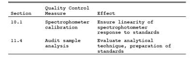
10.1 Spectrophotometer.
10.1.1 Optimum
Wavelength Determination.
10.1.1.1 Calibrate
the wavelength scale of the spectrophotometer every 6 months. The calibration
may be accomplished by using an energy source with an intense line emission
such as a mercury lamp, or by using a series of glass filters spanning the measuring
range of the spectrophotometer. Calibration materials are available
commercially and from the National Institute of Standards and Technology.
Specific details on the use of such materials should be supplied by the vendor;
general information about calibration techniques can be obtained from general
reference books on analytical chemistry. The wavelength scale of the
spectrophotometer must read correctly within 5 nm at all calibration points;
otherwise, repair and recalibrate the spectrophotometer. Once the wavelength
scale of the spectrophotometer is in proper calibration, use 410 nm as the
optimum wavelength for the measurement of the absorbance of the standards and
samples.
10.1.1.2
Alternatively, a scanning procedure may be employed to determine the proper
measuring wavelength. If the instrument is a double-beam spectrophotometer,
scan the spectrum between 400 and 415 nm using a 200 µg NO2 standard solution in the sample cell and a blank solution in the
reference cell. If a peak does not occur, the spectrophotometer is probably
malfunctioning and should be repaired. When a peak is obtained within the 400
to 415 nm range, the wavelength at which this peak occurs shall be the optimum
wavelength for the measurement of absorbance of both the standards and the
samples. For a single-beam spectrophotometer, follow the scanning procedure
described above, except scan separately the blank and standard solutions. The
optimum wavelength shall be the wavelength at which the maximum difference in
absorbance between the standard and the blank occurs.
10.1.2 Determination
of Spectrophotometer Calibration Factor Kc. Add 0
ml, 2.0 ml, 4.0 ml, 6.0 ml, and 8.0 ml of the KNO3 working
standard solution (1 ml = 100 µg NO2) to a
series of five 50-ml volumetric flasks. To each flask, add 25 ml of absorbing
solution and 10 ml water. Add 1 N NaOH to each flask until the pH is between 9
and 12 (about 25 to 35 drops). Dilute to the mark with water. Mix thoroughly,
and pipette a 25-ml aliquot of each solution into a separate porcelain-evaporating
dish. Beginning with the evaporation step, follow the analysis procedure of
Section 11.2 until the solution has been transferred to the 100-ml volumetric
flask and diluted to the mark. Measure the absorbance of each solution at the
optimum wavelength as determined in Section 10.2.1. This calibration procedure
must be repeated on each day that samples are analyzed. Calculate the
spectrophotometer calibration factor as shown in Section 12.2.
10.1.3
Spectrophotometer Calibration Quality Control. Multiply the absorbance value
obtained for each standard by the Kc factor
(reciprocal of the least squares slope) to determine the distance each
calibration point lies from the theoretical calibration line. The difference
between the calculated concentration values and the actual concentrations (i.e., 100, 200, 300, and 400 µg NO2) should be less than 7 percent for all standards.
10.2 Barometer.
Calibrate against a
mercury barometer.
10.3 Temperature Gauge.
Calibrate dial
thermometers against mercury-in-glass thermometers.
10.4 Vacuum Gauge.
Calibrate mechanical
gauges, if used, against a mercury manometer such as that specified in Section
6.1.6.
10.5 Analytical Balance.
Calibrate against
standard weights.
11.0 Analytical Procedures.
11.1 Sample Loss Check.
Note the level of the
liquid in the container, and confirm whether any sample was lost during
shipment. Note this on the analytical data sheet. If a noticeable amount of leakage has occurred, either void
the sample or use methods, subject to the approval of the Administrator, to
correct the final results.
11.2 Sample Preparation.
Immediately prior to
analysis, transfer the contents of the shipping container to a 50 ml volumetric
flask, and rinse the container twice with 5 ml portions of water. Add the rinse
water to the flask, and dilute to mark with water; mix thoroughly. Pipette a
25-ml aliquot into the porcelain evaporating dish. Return any unused portion of
the sample to the polyethylene storage bottle. Evaporate the 25-ml aliquot to
dryness on a steam bath, and allow to cool. Add 2 ml phenoldisulfonic acid
solution to the dried residue, and triturate thoroughly with a polyethylene
policeman. Make sure the solution contacts all the residue. Add 1 ml water and
4 drops of concentrated sulfuric acid. Heat the solution on a steam bath for 3
minutes with occasional stirring. Allow the solution to cool, add 20 ml water,
mix well by stirring, and add concentrated ammonium hydroxide, dropwise, with
constant stirring, until the pH is 10 (as determined by pH paper). If the
sample contains solids, these must be removed by filtration (centrifugation is
an acceptable alternative, subject to the approval of the Administrator) as
follows: Filter through Whatman No. 41 filter paper into a 100-ml volumetric flask.
Rinse the evaporating dish with three 5- ml portions of water. Filter these
three rinses. Wash the filter with at least three 15-ml portions of water. Add
the filter washings to the contents of the volumetric flask, and dilute to the
mark with water. If solids are absent, the solution can be transferred directly
to the 100-ml volumetric flask and diluted to the mark with water.
11.3 Sample Analysis.
Mix the contents of
the flask thoroughly, and measure the absorbance at the optimum wavelength used
for the standards (Section 10.2.1), using the blank solution as a zero
reference. Dilute the sample and the blank with equal volumes of water if the
absorbance exceeds A4, the absorbance of the 400-µg NO2 standard (see Section 10.2.2).
11.4 Audit Sample Analysis.
11.4.1 When the
method is used to analyze samples to demonstrate compliance with a source
emission regulation, an audit sample must be analyzed, subject to availability.
11.4.2 Concurrently analyze
the audit sample and the compliance samples in the same manner to evaluate the
technique of the analyst and the standards preparation.
11.4.3 The same
analyst, analytical reagents, and analytical system must be used for the
compliance samples and the audit sample. If this condition is met, duplicate
auditing of subsequent compliance analyses for the same enforcement agency
within a 30-day period is waived. An audit sample set may not be used to
validate different sets of compliance samples under the jurisdiction of
separate enforcement agencies, unless prior arrangements have been made with
both enforcement agencies.
11.5 Audit Sample Results.
11.5.1 Calculate the
audit sample concentrations and submit results using the instructions provided
with the audit samples.
11.5.2 Report the
results of the audit samples and the compliance determination samples along
with their identification numbers, and the analyst's name to the responsible
enforcement authority. Include this information with reports of any subsequent
compliance analyses for the same enforcement authority during the 30-day
period.
11.5.3 The
concentrations of the audit samples obtained by the analyst must agree within 5
percent of the actual concentration. If the 5 percent specification is not met,
reanalyze the compliance and audit samples, and include initial and reanalysis
values in the test report.
11.5.4 Failure to
meet the 5-percent specification may require retests until the audit problems
are resolved. However, if the audit results do not affect the compliance or
noncompliance status of the affected facility, the Administrator may waive the
reanalysis requirement, further audits, or retests and accept the results of
the compliance test. While steps are being taken to resolve audit analysis
problems, the Administrator may also choose to use the data to determine the
compliance or noncompliance status of the affected facility.
12.0 Data Analysis and Calculations.
Carry out the
calculations, retaining at least one extra significant figure beyond that of
the acquired data. Round off figures after final calculations.
12.1 Nomenclature.
A = Absorbance of
sample.
A1 = Absorbance of the 100-µg NO2 standard.
A2 = Absorbance of the 200-µg NO2 standard.
A3 = Absorbance of the 300-µg NO2 standard.
A4 = Absorbance of the 400-µg NO2 standard.
C = Concentration of
NOx as NO2, dry
basis, corrected to standard conditions, mg/dsm3 (lb/dscf).
Cd = Determined audit sample concentration, mg/dscm.
Ca = Actual audit sample concentration, mg/dscm.
F = Dilution factor (i.e., 25/5, 25/10, etc., required only if sample dilution was needed to
reduce the absorbance into the range of the calibration).
Kc = Spectrophotometer calibration factor.
m = Mass of NOx as NO2 in gas sample, µg.
Pf = Final absolute pressure of flask, mm Hg (in. Hg).
Pi = Initial absolute pressure of flask, mm Hg (in. Hg).
Pstd = Standard absolute pressure, 760 mm Hg (29.92
in. Hg).
RE = Relative error
for QA audit samples, percent.
Tf = Final absolute temperature of flask, °K (°R).
Ti = Initial absolute temperature of flask, °K (°R).
Tstd = Standard absolute temperature, 293 °K (528
°R).
Vsc = Sample volume at standard conditions (dry
basis), ml.
Vf = Volume of flask and valve, ml.
Va = Volume of absorbing solution, 25 ml.
12.2 Spectrophotometer Calibration Factor.
![]()
12.3 Sample Volume, Dry Basis, Corrected to Standard
Conditions.
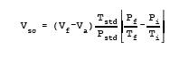
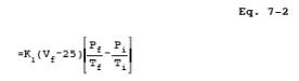
where:
K1 = 0.3858 °K/mm Hg for metric units,
= 17.65 °R/in. Hg for
English units.
12.4 Total µg NO2 per sample.
m = 2 Kc
A F Eq.
7-3
where:
2 = 50/25, the
aliquot factor.
NOTE: If other than a 25-ml aliquot is used for
analysis, the factor 2 must be replaced by a corresponding factor.
12.5 Sample Concentration, Dry Basis, Corrected to Standard Conditions.
C = K2 (m/Vsc) Eq.
7-4
where:
K2 = 103 (mg/m3)/(µg/ml)
for metric units,
= 6.242 x 10⁻⁵ (lb/scf)/(µg/ml) for English units.
12.6 Relative Error for QA Audit Samples.
RE = 100 (Cd
- Ca)/Ca Eq. 7-5
13.0 Method Performance.
13.1 Range. The analytical
range of the method has been determined to be 2 to 400 milligrams NOx (as NO2) per dry standard cubic meter, without having
to dilute the sample.
14.0 Pollution Prevention. [Reserved]
15.0 Waste Management. [Reserved]
16.0 References.
1. Standard Methods
of Chemical Analysis. 6th ed. New York, D. Van Nostrand Co., Inc. 1962. Vol. 1,
pp. 329-330.
2. Standard Method of
Test for Oxides of Nitrogen in Gaseous Combustion Products (Phenoldisulfonic
Acid Procedure). In: 1968 Book of ASTM Standards, Part 26. Philadelphia, PA.
1968. ASTM Designation D 1608-60, pp. 725-729.
3. Jacob, M.B. The
Chemical Analysis of Air Pollutants. New York. Interscience Publishers, Inc.
1960. Vol. 10, pp. 351-356.
4. Beatty, R.L., L.B.
Berger, and H.H. Schrenk. Determination of Oxides of Nitrogen by the
Phenoldisulfonic Acid Method. Bureau of Mines, U.S. Dept. of Interior. R.I.
3687. February 1943.
5. Hamil, H.F. and
D.E. Camann. Collaborative Study of Method for the Determination of Nitrogen
Oxide Emissions from Stationary Sources (Fossil Fuel-Fired Steam Generators).
Southwest Research Institute Report for Environmental Protection Agency.
Research Triangle Park, NC. October 5, 1973.
6. Hamil, H.F. and
R.E. Thomas. Collaborative Study of Method for the Determination of Nitrogen
Oxide Emissions from Stationary Sources (Nitric Acid Plants). Southwest
Research Institute Report for Environmental Protection Agency. Research
Triangle Park, NC. May 8, 1974.
7. Stack Sampling
Safety Manual (Draft). U.S. Environmental Protection Agency, Office of Air
Quality Planning and Standards, Research Triangle Park, NC. September 1978.
17.0 Tables, Diagrams, Flowcharts, and Validation Data.
Figure
7-1. Sampling Train, Flask Valve, and Flask.