METHOD 6B -
DETERMINATION OF SULFUR DIOXIDE AND CARBON DIOXIDE DAILY AVERAGE EMISSIONS FROM
FOSSIL FUEL COMBUSTION SOURCES
NOTE: This method does not include all of the
specifications (e.g.,
equipment and supplies) and procedures (e.g., sampling and analytical) essential to its
performance. Some material is incorporated by reference from other methods in
this part. Therefore, to obtain reliable results, persons using this method
should have a thorough knowledge of at least the following additional test
methods: Method 1, Method 2,
Method 3, Method 5, Method 6, and Method 6A.
6.1 The isopropanol
bubbler is not used.
6.2 For intermittent
operation, include an industrial timer-switch
6.3 Stainless steel
sampling probes, type 316, are not recommended
8.0 Sample Collection,
Preservation, Transport, and Storage.
8.1 Preparation of
Sampling Train.
8.2 Sampling Train
Leak-Check Procedure.
10.0 Calibration and
Standardization.
10.1 Periodic
Calibration Check.
11.1 Sample Loss Check
and Analysis.
11.2 Quality Assurance
(QA) Audit Samples.
12.0 Data Analysis and
Calculations.
13.2 Repeatability and
Reproducibility.
14.0 Pollution
Prevention. [Reserved]
15.0 Waste Management.
[Reserved]
18.0 Tables, Diagrams,
Flowcharts, and Validation Data.
1.0 Scope and Application.
1.1 Analytes.
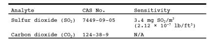
1.2 Applicability.
This method is
applicable for the determination of SO2 emissions
from combustion sources in terms of concentration (ng/dscm or lb/dscf) and emission
rate (ng/J or lb/106
Btu), and for the determination of
CO2 concentration (percent) on a daily (24 hours)
basis.
1.3 Data Quality Objectives.
Adherence to the
requirements of this method will enhance the quality of the data obtained from
air pollutant sampling methods.
2.0 Summary of Method.
2.1 A gas sample is
extracted from the sampling point in the stack intermittently over a 24-hour or
other specified time period. The SO2 fraction
is measured by the barium-thorin titration method. Moisture and CO2 fractions are collected in the same sampling train, and are
determined gravimetrically.
3.0 Definitions. [Reserved]
4.0 Interferences.
Same as Method 6, Section 4.0.
5.0 Safety.
5.1 Disclaimer.
This method may
involve hazardous materials, operations, and equipment. This test method may
not address all of the safety problems associated with its use. It is the
responsibility of the user to establish appropriate safety and health practices
and determine the applicability of regulatory limitations prior to performing
this test method.
5.2 Corrosive Reagents.
Same as Method 6, Section 5.2.
6.0 Equipment and Supplies.
Same as Method 6A, Section 6.0, with the following exceptions
and additions:
6.1 The isopropanol bubbler is not used.
An empty bubbler for
the collection of liquid droplets , that does not allow direct contact between
the collected liquid and the gas sample, may be included in the sampling train.
6.2 For intermittent operation, include an industrial timer-switch
For intermittent
operation, include an industrial timer-switch designed to operate in the
"on" position at least 2 minutes continuously and "off" the
remaining period over a repeating cycle. The cycle of operation is designated
in the applicable regulation. At a minimum, the sampling operation should
include at least 12, equal, evenly-spaced periods per 24 hours.
6.3 Stainless steel sampling probes, type 316, are not recommended
Stainless steel
sampling probes, type 316, are not recommended for use with Method 6B because
of potential sample contamination due to corrosion. Glass probes or other types
of stainless steel, e.g.,
Hasteloy or Carpenter 20, are recommended for long-term use.
NOTE: For applications downstream of wet scrubbers,
a heated out-of-stack filter (either borosilicate glass wool or glass fiber
mat) is necessary. Probe and filter heating systems capable of maintaining a
sample gas temperature of between 20 and 120 ˚C (68 and 248 ˚F) at the filter
are also required in these cases. The electric supply for these heating systems
should be continuous and separate from the timed operation of the sample pump.
7.0 Reagents and Standards.
Same as Method 6A, Section 7.0, with the following exceptions:
7.1 Isopropanol is
not used for sampling.
7.2 The hydrogen
peroxide absorbing solution shall be diluted to no less than 6 percent by
volume, instead of 3 percent as specified in Methods 6 and 6A.
7.3 If the Method 6B
sampling train is to be operated in a low sample flow condition (less than 100
ml/min or 0.21 ft3/hr), molecular sieve material may be
substituted for Ascarite II as the CO2 absorbing
material. The recommended molecular sieve material is Union Carbide 1/16 inch
pellets, 5 A˚, or equivalent. Molecular sieve material need not be discarded
following the sampling run, provided that it is regenerated as per the
manufacturer's instruction. Use of molecular sieve material at flow rates
higher than 100 ml/min (0.21 ft3/hr) may cause
erroneous CO2 results.
8.0 Sample Collection, Preservation, Transport, and Storage.
8.1 Preparation of Sampling Train.
Same as Method 6A, Section 8.1, with the addition of
the following:
8.1.1 The sampling
train is assembled as shown in Figure 6A-1 of
Method 6A, except that the isopropanol bubbler is not included.
8.1.2 Adjust the
timer-switch to operate in the "on" position from 2 to 4 minutes on a
2-hour repeating cycle or other cycle specified in the applicable regulation.
Other timer sequences may be used with the restriction that the total sample
volume collected is between 25 and 60 liters (0.9 and 2.1 ft3) for the amounts of sampling reagents prescribed in this method.
8.1.3 Add cold water
to the tank until the impingers and bubblers are covered at least two-thirds of
their length. The impingers and bubbler tank must be covered and protected from
intense heat and direct sunlight. If freezing conditions exist, the impinger
solution and the water bath must be protected.
NOTE: Sampling may be conducted continuously if a low
flow-rate sample pump [20 to 40 ml/min (0.04 to 0.08 ft3/hr) for the reagent volumes described in this method] is used. If
sampling is continuous, the timer-switch is not necessary. In addition, if the
sample pump is designed for constant rate sampling, the rate meter may be
deleted. The total gas volume collected should be between 25 and 60 liters (0.9
and 2.1 ft3) for the amounts of sampling reagents
prescribed in this method.
8.2 Sampling Train Leak-Check Procedure.
Same as Method 6, Section 8.2.
8.3 Sample Collection.
8.3.1 The probe and
filter (either in-stack, out-of-stack, or both) must be heated to a temperature
sufficient to prevent water condensation.
8.3.2 Record the
initial dry gas meter reading. To begin sampling, position the tip of the probe
at the sampling point, connect the probe to the first impinger (or filter), and
start the timer and the sample pump. Adjust the sample flow to a constant rate
of approximately 1.0 liter/min (0.035 cfm) as indicated by the rotameter.
Observe the operation of the timer, and determine that it is operating as
intended (i.e., the timer is
in the "on" position for the desired period, and the cycle repeats as
required).
8.3.3 One time
between 9:00 a.m. and 11:00 a.m. during the 24-hour sampling period, record the
dry gas meter temperature (Tm) and the barometric
pressure (P(bar)).
8.3.4 At the
conclusion of the run, turn off the timer and the sample pump, remove the probe
from the stack, and record the final gas meter volume reading. Conduct a leak-
check as described in Section 8.2. If a leak is found, void the test run or use
procedures acceptable to the Administrator to adjust the sample volume for
leakage. Repeat the steps in Sections 8.3.1 to 8.3.4 for successive runs.
8.4 Sample Recovery.
The procedures for
sample recovery (moisture measurement, peroxide solution, and CO2 absorber) are the same as those in Method
6A, Section 8.3.
9.0 Quality Control.
Same as Method 6, Section 9.0., with the exception of the
isopropanol-check.
10.0 Calibration and Standardization.
Same as Method 6, Section 10.0, with the addition of
the following:
10.1 Periodic Calibration Check.
After 30 days of
operation of the test train, conduct a calibration check according to the same
procedures as the post-test calibration check (Method 6, Section 10.1.2). If
the deviation between initial and periodic calibration factors exceeds 5
percent, use the smaller of the two factors in calculations for the preceding
30 days of data, but use the most recent calibration factor for succeeding test
runs.
11.0 Analytical Procedures.
11.1 Sample Loss Check and Analysis.
Same as Method 6, Sections 11.1 and 11.2, respectively.
11.2 Quality Assurance (QA) Audit Samples.
Analysis of QA audit
samples is required only when this method is used for compliance
determinations. Obtain an audit sample set as directed in Section 7.3.6 of
Method 6. Analyze the audit samples at least once for every 30 days of sample
collection, and report the results as directed in Section 11.3 of Method 6. The
analyst performing the sample analyses shall perform the audit analyses. If
more than one analyst performs the sample analyses during the 30-day sampling
period, each analyst shall perform the audit analyses and all audit results
shall be reported. Acceptance criteria for the audit results are the same as
those in Method 6.
12.0 Data Analysis and Calculations.
Same as Method 6A, Section 12.0, except that Pbar and Tm correspond
to the values recorded in Section 8.3.3 of this method. The values are as
follows:
Pbar = Initial barometric pressure for the test
period, mm Hg.
Tm = Absolute meter temperature for the test period, ˚K.
13.0 Method Performance.
13.1 Range.
13.1.1 Sulfur
Dioxide. Same as Method 6.
13.1.2 Carbon
Dioxide. Not determined.
13.2 Repeatability and Reproducibility.
EPA-sponsored
collaborative studies were undertaken to determine the magnitude of
repeatability and reproducibility achievable by qualified testers following the
procedures in this method. The results of the studies evolve from field tests
including comparisons with Methods 3 and 6. For measurements of emission rates
from wet, flue gas desulfurization units in (ng/J), the repeatability
(intralaboratory precision) is 8.0 percent and the reproducibility
(inter-laboratory precision) is 11.1 percent.
14.0 Pollution Prevention. [Reserved]
15.0 Waste Management. [Reserved]
16.0 Alternative Methods.
Same as Method 6A, Section 16.0, except that the timer
is needed and is operated as outlined in this method.
17.0 References.
Same as Method 6A, Section 17.0, with the addition of
the following:
1. Butler, Frank E., et.
al. The Collaborative Test of
Method 6B: Twenty-Four-Hour Analysis of SO2 and CO2. JAPCA. Vol. 33, No. 10. October 1983.
18.0 Tables, Diagrams, Flowcharts, and Validation Data.
[Reserved]