METHOD 6A -
DETERMINATION OF SULFUR DIOXIDE, MOISTURE, AND CARBON DIOXIDE FROM FOSSIL FUEL
COMBUSTION SOURCES
NOTE: This method does not include all of the
specifications (e.g.,
equipment and supplies) and procedures (e.g., sampling and analytical) essential to its
performance. Some material is incorporated by reference from other methods in
this part. Therefore, to obtain reliable results, persons using this method
should have a thorough knowledge of at least the following additional test
methods: Method 1, Method
2, Method 3, Method 5,
Method 6, and Method 19.
6.1.1.1 Impingers and
Bubblers.
7.2 Sample Recovery and
Analysis.
8.0 Sample Collection,
Preservation, Transport, and Storage.
8.1 Preparation of
Sampling Train.
8.2 Sampling Train
Leak-Check Procedure and Sample Collection.
10.0 Calibration and
Standardization.
11.2 Quality Assurance
(QA) Audit Samples.
12.0 Data Analysis and
Calculations.
12.2 CO2 Volume
Collected, Corrected to Standard Conditions.
12.3 Moisture Volume
Collected, Corrected to Standard Conditions.
14.0 Pollution
Prevention. [Reserved]
15.0 Waste Management.
[Reserved]
16.2 Preparation of the
Sampling Train.
16.3 Sampling Train
Leak-Check Procedure and Sample Collection.
18.0 Tables, Diagrams,
Flowcharts, and Validation Data.
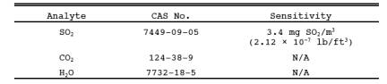
1.0 Scope and Application.
1.1 Analytes.
1.2 Applicability.
This method is
applicable for the determination of sulfur dioxide (SO2) emissions from fossil fuel combustion sources in terms of
concentration (mg/dscm or lb/dscf) and in terms of emission rate (ng/J or lb/106 Btu) and for the determination of carbon dioxide (CO2) concentration (percent). Moisture content (percent), if desired,
may also be determined by this method.
1.3 Data Quality Objectives.
Adherence to the
requirements of this method will enhance the quality of the data obtained from
air pollutant sampling methods.
2.0 Summary of Method.
2.1 A gas sample is
extracted from a sampling point in the stack. The SO2 and the sulfur trioxide, including those fractions in any sulfur
acid mist, are separated. The SO2 fraction is measured
by the barium-thorin titration method. Moisture and CO2 fractions are collected in the same sampling train, and are
determined gravimetrically.
3.0 Definitions. [Reserved]
4.0 Interferences.
Same as Method 6,
Section 4.0.
5.0 Safety.
5.1 Disclaimer.
This method may
involve hazardous materials, operations, and equipment. This test method may
not address all of the safety problems associated with its use. It is the
responsibility of the user to establish appropriate safety and health practices
and determine the applicability of regulatory limitations prior to performing
this test method.
5.2 Corrosive reagents.
Same as Method 6, Section 5.2.
6.0 Equipment and Supplies.
6.1 Sample Collection.
Same as Method 6,
Section 6.1, with the exception of the following:
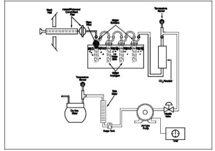
6.1.1 Sampling Train.
A schematic of the sampling
train used in this method is shown in Figure 6A-1.
6.1.1.1 Impingers and Bubblers.
Two 30-ml midget
impingers with a 1-mm restricted tip and two 30-ml midget bubblers with
unrestricted tips. Other types of impingers and bubblers (e.g., Mae West for SO2 collection
and rigid cylinders containing Drierite for moisture absorbers), may be used
with proper attention to reagent volumes and levels, subject to the approval of
the Administrator.
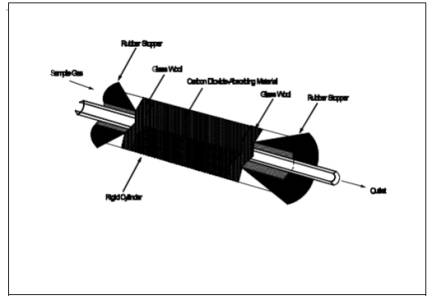
6.1.1.2 CO2 Absorber.
A sealable rigid cylinder
or bottle with an inside diameter between 30 and 90 mm , a length between 125
and 250 mm, and appropriate connections at both ends. The filter may be a
separate heated unit or may be within the heated portion of the probe. If the
filter is within the sampling probe, the filter should not be within 15 cm of
the probe inlet or any unheated section of the probe, such as the connection to
the first bubbler. The probe and filter should be heated to at least 20 ˚C (68
˚F) above the source temperature, but not greater than 120 ˚C (248 ˚F). The
filter temperature (i.e.,
the sample gas temperature) should be monitored to assure the desired
temperature is maintained. A heated Teflon connector may be used to connect the
filter holder or probe to the first impinger.
NOTE: For applications downstream of wet scrubbers, a
heated out-of-stack filter (either borosilicate glass wool or glass fiber mat)
is necessary.
6.2 Sample Recovery.
Same as Method 6,
Section 6.2.
6.3 Sample Analysis.
Same as Method 6,
Section 6.3, with the addition of a balance to measure within 0.05 g.
7.0 Reagents and Standards.
NOTE: Unless otherwise indicated, all reagents must
conform to the specifications established by the Committee on Analytical
Reagents of the American Chemical Society. Where such specifications are not
available, use the best available grade.
7.1 Sample Collection.
Same as Method 6,
Section 7.1, with the addition of the following:
7.1.1 Drierite.
Anhydrous calcium sulfate (CaSO4) desiccant, 8 mesh, indicating
type is recommended.
NOTE: Do not use silica gel or similar desiccant in
this application.
7.1.2 CO2 Absorbing Material. Ascarite II. Sodium hydroxide-coated silica, 8-
to 20-mesh.
7.2 Sample Recovery and Analysis.
Same as Method 6,
Sections 7.2 and 7.3, respectively.
8.0 Sample Collection, Preservation, Transport, and Storage.
8.1 Preparation of Sampling Train.
8.1.1 Measure 15 ml
of 80 percent isopropanol into the first midget bubbler and 15 ml of 3 percent
hydrogen peroxide into each of the two midget impingers (the second and third
vessels in the train) as described in Method 6, Section 8.1. Insert the glass wool into the top of the
isopropanol bubbler as shown in Figure 6A-1. Place about 25 g of Drierite into
the second midget bubbler (the fourth vessel in the train). Clean the outside
of the bubblers and impingers and allow the vessels to reach room temperature.
Weigh the four vessels simultaneously to the nearest 0.1 g, and record this
initial weight (mwi).
8.1.2 With one end of
the CO2 absorber sealed, place glass wool into the
cylinder to a depth of about 1 cm (0.5 in.). Place about 150 g of CO2 absorbing material in the cylinder on top of the glass wool, and
fill the remaining space in the cylinder with glass wool. Assemble the cylinder
as shown in Figure 6A-2. With the cylinder in a horizontal position, rotate it
around the horizontal axis. The CO2 absorbing
material should remain in position during the rotation, and no open spaces or
channels should be formed. If necessary, pack more glass wool into the cylinder
to make the CO2 absorbing material stable. Clean the outside of
the cylinder of loose dirt and moisture and allow the cylinder to reach room
temperature. Weigh the cylinder to the nearest 0.1 g, and record this initial
weight (mai).
8.1.3 Assemble the
train as shown in Figure 6A-1. Adjust the probe heater to a temperature
sufficient to prevent condensation (see NOTE in Section 6.1). Place crushed ice and water
around the impingers and bubblers. Mount the CO2 absorber
outside the water bath in a vertical flow position with the sample gas inlet at
the bottom. Flexible tubing (e.g.,
Tygon) may be used to connect the last SO2 absorbing
impinger to the moisture absorber and to connect the moisture absorber to the
CO2 absorber. A second, smaller CO2 absorber containing Ascarite II may be added in-line downstream of
the primary CO2 absorber as a breakthrough indicator. Ascarite
II turns white when CO2
is absorbed.
8.2 Sampling Train Leak-Check Procedure and Sample Collection.
Same as Method 6,
Sections 8.2 and 8.3, respectively.
8.3 Sample Recovery.
8.3.1 Moisture
Measurement. Disconnect the isopropanol bubbler, the SO2 impingers, and the moisture absorber from the sample train. Allow
about 10 minutes for them to reach room temperature, clean the outside of loose
dirt and moisture, and weigh them simultaneously in the same manner as in
Section 8.1. Record this final weight (mwf).
8.3.2 Peroxide
Solution. Discard the contents of the isopropanol bubbler and pour the contents
of the midget impingers into a leak-free polyethylene bottle for shipping.
Rinse the two midget impingers and connecting tubes with water, and add the
washing to the same storage container.
8.3.3 CO2 Absorber. Allow the CO2 absorber
to warm to room temperature (about 10 minutes), clean the outside of loose dirt
and moisture, and weigh to the nearest 0.1 g in the same manner as in Section
8.1. Record this final weight (maf). Discard used
Ascarite II material.
9.0 Quality Control.
Same as Method 6,
Section 9.0.
10.0 Calibration and Standardization.
Same as Method 6,
Section 10.0.
11.0 Analytical Procedure.
11.1 Sample Analysis.
The sample analysis
procedure for SO2 is the same as that specified in Method 6,
Section 11.0.
11.2 Quality Assurance (QA) Audit Samples.
Analysis of QA audit
samples is required only when this method is used for compliance
determinations. Obtain an audit sample
set as directed in Section 7.3.6 of Method 6. Analyze the audit samples,
and report the results as directed in Section 11.3 of Method 6. Acceptance
criteria for the audit results are the same as those in Method 6.
12.0 Data Analysis and Calculations.
Same as Method 6,
Section 12.0, with the addition of the following:
12.1 Nomenclature.
Cw = Concentration of moisture, percent.
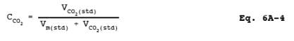
CCO2 =
Concentration of CO2, dry basis, percent.
ESO2 =
Emission rate of SO2, ng/J (lb/106 Btu).
FC = Carbon F-factor from Method 19 for the fuel burned, dscm/J
(dscf/106 Btu).
mwi = Initial weight of impingers, bubblers, and
moisture absorber, g.
mwf = Final weight of impingers, bubblers, and
moisture absorber, g.
mai = Initial weight of CO2 absorber, g.
maf = Final weight of CO2 absorber, g.
mSO2 = Mass of SO2 collected,
mg.
VCO2(std) = Equivalent
volume of CO2 collected at standard conditions, dscm (dscf).
Vw(std) = Equivalent volume of moisture collected at
standard conditions, scm (scf).
12.2 CO2 Volume Collected, Corrected
to Standard Conditions.
![]()
where:
K3 = Equivalent volume of gaseous CO2 at
standard conditions, 5.467 x 10⁻⁴ dscm/g (1.930 x 10⁻² dscf/g).
12.3 Moisture Volume Collected, Corrected to Standard Conditions.
![]()
where:
K4 = Equivalent volume of water vapor at standard conditions, 1.336 x
10-3 scm/g (4.717 x 10⁻² scf/g).
12.4 SO2 Concentration.
where:
K2 = 32.03 mg SO2/meq. SO2 (7.061 x
10-5 lb SO2/meq. SO2)
12.5 CO2 Concentration.
12.6 Moisture Concentration.
13.0 Method Performance.
13.1 Range and Precision.
The minimum detectable limit and the upper limit for the measurement of SO2 are the same as for Method 6. For a 20-liter sample, this method
has a precision of ±0.5 percent CO2 for
concentrations between 2.5 and 25 percent CO2 and ± 1.0
percent moisture for moisture concentrations greater than 5 percent.
14.0 Pollution Prevention. [Reserved]
15.0 Waste Management. [Reserved]
16.0 Alternative Methods.
If the only emission
measurement desired is in terms of emission rate of SO2 (ng/J or lb/106
Btu), an abbreviated procedure may
be used. The differences between the above procedure and the abbreviated
procedure are described below.
16.1 Sampling Train.
The sampling train is
the same as that shown in Figure 6A-1 and as described in Section 6.1, except
that the dry gas meter is not needed.
16.2 Preparation of the Sampling Train.
Follow the same
procedure as in Section 8.1, except do not weigh the isopropanol bubbler, the
SO2 absorbing impingers, or the moisture absorber.
16.3 Sampling Train Leak-Check Procedure and Sample Collection.
Leak-check and
operate the sampling train as described in Section 8.2, except that dry gas
meter readings, barometric pressure, and dry gas meter temperatures need not be
recorded during sampling.
16.4 Sample Recovery.
Follow the procedure
in Section 8.3, except do not weigh the isopropanol bubbler, the SO2 absorbing impingers, or the moisture absorber.
16.5 Sample Analysis.
Analysis of the
peroxide solution and QA audit samples is the same as that described in
Sections 11.1 and 11.2, respectively.
16.6 Calculations.
16.6.1 SO2 Collected.
![]()
where:
K2 = 32.03 mg SO2/meq. SO2
= 7.061 x 10⁻⁵ lb SO2/meq. SO2
16.6.2 Sulfur Dioxide
Emission Rate.
![]()
where:
K5 = 1.829 x10⁹
mg/dscm
= 0.1142 lb/dscf
17.0 References.
Same as Method 6,
Section 17.0, References 1 through 8, with the addition of the following:
1. Stanley, Jon and
P.R. Westlin. An Alternate Method for Stack Gas Moisture Determination. Source Evaluation
Society Newsletter. 3(4). November 1978.
2. Whittle, Richard
N. and P.R. Westlin. Air Pollution Test Report: Development and Evaluation of
an Intermittent Integrated SO2/CO2 Emission Sampling Procedure. Environmental Protection Agency,
Emission Standard and Engineering Division, Emission Measurement Branch.
Research Triangle Park, NC. December 1979. 14 pp.
18.0 Tables, Diagrams, Flowcharts, and Validation Data.