METHOD
3B - GAS ANALYSIS FOR THE DETERMINATION OF EMISSION RATE CORRECTION FACTOR OR
EXCESS AIR
NOTE: This method does not include all of the
specifications (e.g.,
equipment and supplies) and procedures (e.g., sampling) essential to its performance. Some
material is incorporated by reference from other methods in this part.
Therefore, to obtain reliable results, persons using this method should have a
thorough knowledge of at least the following additional test methods: Method 1 and 3.
1.3 Other methods, as
well as modifications
6.1 Grab Sampling and
Integrated Sampling.
6.2 Analysis. An Orsat
analyzer only.
8.0 Sample Collection,
Preservation, Storage, and Transport.
8.1 Single-Point, Grab
Sampling and Analytical Procedure.
8.2 Single-Point,
Integrated Sampling and Analytical Procedure.
8.3 Multi-Point,
Integrated Sampling and Analytical Procedure.
10.0 Calibration and
Standardization.
11.3 Integrated Sample
Analysis.
12.0 Calculations and
Data Analysis.
13.0 Method
Performance. [Reserved]
14.0 Pollution
Prevention. [Reserved]
15.0 Waste Management.
[Reserved]
17.0 Tables, Diagrams,
Flowcharts, and Validation Data.
1.0 Scope and Application.
1.1 Analytes.
1.2 Applicability.
This method is
applicable for the determination of O2, CO2, and CO concentrations in the effluent from fossil-fuel combustion
processes for use in excess air or emission rate correction factor
calculations. Where compounds other than CO2, O2, CO, and nitrogen (N2) are
present in concentrations sufficient to affect the results, the calculation
procedures presented in this method must be modified, subject to the approval
of the Administrator.
1.3 Other methods, as well as modifications
Other methods, as
well as modifications to the procedure described herein, are also applicable
for all of the above determinations. Examples of specific methods and
modifications include: (1) a multi-point sampling method using an Orsat
analyzer to analyze individual grab samples obtained at each point, and (2) a method
using CO2 or O2 and
stoichiometric calculations to determine excess air. These methods and
modifications may be used, but are subject to the approval of the
Administrator.
1.4 Data Quality Objectives.
Adherence to the
requirements of this method will enhance the quality of the data obtained from
air pollutant sampling methods.
2.0 Summary of Method.
2.1 A gas sample is
extracted from a stack by one of the following methods: (1) single-point, grab
sampling; (2) single-point, integrated sampling; or (3) multi-point, integrated
sampling. The gas sample is analyzed for percent CO2, percent O2, and, if necessary, percent CO using an Orsat
combustion gas analyzer.
3.0 Definitions. [Reserved]
4.0 Interferences.
4.1 Several compounds
can interfere, to varying degrees, with the results of Orsat analyses.
Compounds that interfere with CO2 concentration
measurement include acid gases (e.g., sulfur dioxide, hydrogen chloride); compounds that interfere with
O2 concentration measurement include unsaturated
hydrocarbons (e.g., acetone,
acetylene), nitrous oxide, and ammonia. Ammonia reacts chemically with the O2 absorbing solution, and when present in the effluent gas stream
must be removed before analysis.
5.0 Safety.
5.1 Disclaimer.
This method may
involve hazardous materials, operations, and equipment. This test method may
not address all of the safety problems associated with its use. It is the
responsibility of the user of this test method to establish appropriate safety
and health practices and determine the applicability of regulatory limitations
prior to performing this test method.
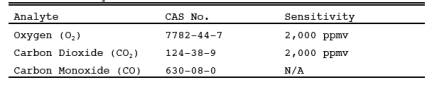
5.2 Corrosive Reagents.
A typical Orsat
analyzer requires four reagents: a gas-confining solution, CO2 absorbent, O2
absorbent, and CO absorbent. These
reagents may contain potassium hydroxide, sodium hydroxide, cuprous chloride,
cuprous sulfate, alkaline pyrogallic acid, and/or chromous chloride. Follow
manufacturer's operating instructions and observe all warning labels for
reagent use.
6.0 Equipment and Supplies.
NOTE: As an alternative to the sampling apparatus and
systems described herein, other sampling systems (e.g., liquid displacement) may be used, provided
such systems are capable of obtaining a representative sample and maintaining a
constant sampling rate, and are, otherwise, capable of yielding acceptable
results. Use of such systems is subject to the approval of the Administrator.
6.1 Grab Sampling and Integrated Sampling.
Same as in Sections 6.1 and 6.2,
respectively for Method 3.
6.2 Analysis. An Orsat analyzer only.
For low CO2 (less than 4.0 percent) or high O2 (greater
than 15.0 percent) concentrations, the measuring burette of the Orsat must have
at least 0.1 percent subdivisions. For Orsat maintenance and operation
procedures, follow the instructions recommended by the manufacturer, unless
otherwise specified herein.
7.0 Reagents and Standards.
7.1 Reagents.
Same as in Method 3, Section 7.1.
7.2 Standards.
Same as in Method 3, Section 7.2.
8.0 Sample Collection, Preservation, Storage, and Transport.
NOTE: Each of the three procedures below shall be used
only when specified in an applicable subpart of the standards. The use of these
procedures for other purposes must have specific prior approval of the
Administrator. A Fyrite-type combustion gas analyzer is not acceptable for
excess air or emission rate correction factor determinations, unless approved
by the Administrator. If both percent CO2 and
percent O2 are measured, the analytical results of any of
the three procedures given below may also be used for calculating the dry
molecular weight (see Method 3).
8.1 Single-Point, Grab Sampling and Analytical Procedure.
8.1.1 The sampling
point in the duct shall either be at the centroid of the cross section or at a
point no closer to the walls than 1.0 m (3.3 ft), unless otherwise specified by
the Administrator.
8.1.2 Set up the
equipment as shown in Figure 3-1 of Method 3,
making sure all connections ahead of the analyzer are tight. Leak-check the
Orsat analyzer according to the procedure described in Section 11.5 of Method 3. This leak-check is
mandatory.
8.1.3 Place the probe
in the stack, with the tip of the probe positioned at the sampling point; purge
the sampling line long enough to allow at least five exchanges. Draw a sample
into the analyzer. For emission rate correction factor determinations,
immediately analyze the sample for percent CO2 or
percent O2, as outlined in Section 11.2. For excess air
determination, immediately analyze the sample for percent CO2, O2, and CO, as outlined in Section
11.2, and calculate excess air as outlined in Section
12.2.
8.1.4 After the
analysis is completed, leak-check (mandatory) the Orsat analyzer once again, as
described in Section 11.5 of Method 3. For the results of the analysis to be
valid, the Orsat analyzer must pass this leak-test before and after the
analysis.
8.2 Single-Point, Integrated Sampling and Analytical Procedure.
8.2.1 The sampling
point in the duct shall be located as specified in Section 8.1.1.
8.2.2 Leak-check (mandatory)
the flexible bag as in Section 6.2.6 of Method 3. Set up the equipment as shown
in Figure 3-2 of Method 3. Just before sampling,
leak-check (mandatory) the train by placing a vacuum gauge at the condenser inlet,
pulling a vacuum of at least 250 mm Hg (10 in. Hg), plugging the outlet at the
quick disconnect, and then turning off the pump. The vacuum should remain
stable for at least 0.5 minute. Evacuate the flexible bag. Connect the probe,
and place it in the stack, with the tip of the probe positioned at the sampling
point; purge the sampling line. Next, connect the bag, and make sure that all
connections are tight.
8.2.3 Sample at a
constant rate, or as specified by the Administrator. The sampling run must be
simultaneous with, and for the same total length of time as, the pollutant
emission rate determination. Collect at least 28 liters (1.0 ft3) of sample gas. Smaller volumes may be collected, subject to
approval of the Administrator.
8.2.4 Obtain one integrated
flue gas sample during each pollutant emission rate determination. For emission
rate correction factor determination, analyze the sample within 4 hours after
it is taken for percent CO2
or percent O2 (as outlined in Section 11.2).
8.3 Multi-Point, Integrated Sampling and Analytical Procedure.
8.3.1 Unless
otherwise specified in an applicable regulation, or by the Administrator, a
minimum of eight traverse points shall be used for circular stacks having
diameters less than 0.61 m (24 in.), a minimum of nine shall be used for
rectangular stacks having equivalent diameters less than 0.61 m (24 in.), and a
minimum of 12 traverse points shall be used for all other cases. The traverse
points shall be located according to Method 1.
8.3.2 Follow the procedures
outlined in Sections 8.2.2 through 8.2.4, except for the following: Traverse
all sampling points, and sample at each point for an equal length of time.
Record sampling data as shown in Figure 3-3 of
Method 3.
9.0 Quality Control.
9.1 Data Validation
Using Fuel Factor. Although in most instances, only CO2 or O2 measurement is required, it is recommended that
both CO2 and O2 be
measured to provide a check on the quality of the data. The data validation
procedure of Section 12.3 is suggested.
NOTE: Since this method for validating the CO2 and O2 analyses is based on combustion of organic and
fossil fuels and dilution of the gas stream with air, this method does not
apply to sources that (1) remove CO2 or O2 through processes other than combustion, (2) add O2 (e.g., oxygen
enrichment) and N2 in proportions different from that of air, (3)
add CO2 (e.g., cement or lime kilns), or (4) have no fuel factor, Fo, values obtainable (e.g., extremely variable waste mixtures). This method validates the
measured proportions of CO2
and O2 for
fuel type, but the method does not detect sample dilution resulting from leaks
during or after sample collection. The method is applicable for samples
collected downstream of most lime or limestone flue-gas desulfurization units
as the CO2 added or removed from the gas stream is not
significant in relation to the total CO2 concentration.
The CO2 concentrations from other types of scrubbers using
only water or basic slurry can be significantly affected and would render the
fuel factor check minimally useful.
10.0 Calibration and Standardization.
10.1 Analyzer.
The analyzer and
analyzer operator technique should be audited periodically as follows: take a
sample from a manifold containing a known mixture of CO2 and O2, and analyze according to the procedure in
Section 11.3. Repeat this procedure until the measured concentration of three
consecutive samples agrees with the stated value ±0.5 percent. If necessary,
take corrective action, as specified in the analyzer users manual.
10.2 Rotameter.
The rotameter need
not be calibrated, but should be cleaned and maintained according to the
manufacturer's instruction.
11.0 Analytical Procedure.
11.1 Maintenance.
The Orsat analyzer
should be maintained according to the manufacturers specifications.
11.2 Grab Sample Analysis.
To ensure complete
absorption of the CO2, O2, or if
applicable, CO, make repeated passes through each absorbing solution until two
consecutive readings are the same. Several passes (three or four) should be
made between readings. (If constant readings cannot be obtained after three
consecutive readings, replace the absorbing solution.) Although in most cases,
only CO2 or O2 concentration
is required, it is recommended that both CO2 and O2 be measured, and that the procedure in Section 12.3 be used to
validate the analytical data.
NOTE: Since this single-point, grab sampling and
analytical procedure is normally conducted in conjunction with a single-point,
grab sampling and analytical procedure for a pollutant, only one analysis is
ordinarily conducted. Therefore, great care must be taken to obtain a valid
sample and analysis.
11.3 Integrated Sample Analysis.
The Orsat analyzer
must be leak-checked (see Section 11.5 of Method 3) before the analysis. If
excess air is desired, proceed as follows: (1) within 4 hours after the sample
is taken, analyze it (as in Sections 11.3.1 through 11.3.3) for percent CO2, O2, and CO; (2) determine the percentage of the
gas that is N2 by subtracting the sum of the percent CO2, percent O2, and percent CO from 100 percent; and (3)
calculate percent excess air, as outlined in Section 12.2.
11.3.1 To ensure
complete absorption of the CO2, O2, or if applicable, CO, follow the procedure described in Section
11.2.
NOTE: Although in most instances only CO2 or O2 is required, it is recommended that both CO2 and O2 be measured, and that the procedures in Section
12.3 be used to validate the analytical data.
11.3.2 Repeat the
analysis until the following criteria are met:
11.3.2.1 For percent
CO2, repeat the analytical procedure until the
results of any three analyses differ by no more than (a) 0.3 percent by volume
when CO2 is greater than 4.0 percent or (b) 0.2 percent
by volume when CO2 is less than or equal to 4.0 percent. Average
three acceptable values of percent CO2, and
report the results to the nearest 0.2 percent.
11.3.2.2 For percent
O2, repeat the analytical procedure until the
results of any three analyses differ by no more than (a) 0.3 percent by volume
when O2 is less than 15.0 percent or (b) 0.2 percent by
volume when O2 is greater than or equal to 15.0 percent.
Average the three acceptable values of percent O2,
and report the results to the nearest 0.1 percent.
11.3.2.3 For percent
CO, repeat the analytical procedure until the results of any three analyses
differ by no more than 0.3 percent. Average the three acceptable values of
percent CO, and report the results to the nearest 0.1 percent.
11.3.3 After the
analysis is completed, leak-check (mandatory) the Orsat analyzer once again, as
described in Section 11.5 of Method 3. For the results of the analysis to be
valid, the Orsat analyzer must pass this leak-test before and after the analysis.
11.4 Standardization.
A periodic check of
the reagents and of operator technique should be conducted at least once every
three series of test runs as indicated in
Section 10.1.
12.0 Calculations and Data Analysis.
12.1 Nomenclature.
Same as Section 12.1 of Method 3 with the
addition of the following:
%EA = Percent excess
air.
0.264 = Ratio of O2 to N2 in air, v/v.
12.2
Percent Excess Air. Determine the percentage of the gas that is N2 by subtracting the sum of the percent CO2, percent CO, and percent O2 from 100
percent. Calculate the percent excess air (if applicable) by substituting the
appropriate values of percent O2, CO, and N2 into Equation 3B-1.
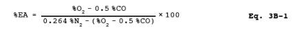
NOTE: The equation above assumes that ambient air is
used as the source of O2
and that the fuel does not contain
appreciable amounts of N2
(as do coke oven or blast furnace
gases). For those cases when appreciable amounts of N2 are present (coal, oil, and natural gas do not contain appreciable
amounts of N2) or when oxygen enrichment is used, alternative
methods, subject to approval of the Administrator, are required.
12.3 Data Validation
When Both CO2 and O2 Are
Measured.
12.3.1 Fuel Factor, Fo. Calculate the fuel factor (if applicable) using Equation 3B-2:
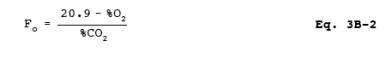
where:
%O2 = Percent O2
by volume, dry basis.
%CO2 = Percent CO2
by volume, dry basis.
20.9 = Percent O2 by volume in ambient air.
If CO is present in
quantities measurable by this method, adjust the O2 and CO2
values using Equations 3B-3 and
3B-4 before performing the calculation for Fo:
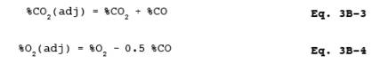
where:
%CO = Percent CO by
volume, dry basis.
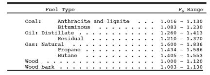
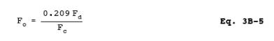
12.3.2 Compare the
calculated Fo factor with the expected Fo values. Table 3B-1 in Section 17.0 may be
used in establishing acceptable ranges for the expected Fo if the fuel being burned is known. When fuels are burned in
combinations, calculate the combined fuel Fd and Fc factors (as defined in Method 19,
Section 12.2) according to the procedure in Method 19, Sections 12.2 and 12.3.
Then calculate the Fo
factor according to Equation 3B-5.
12.3.3 Calculated Fo values, beyond the acceptable ranges shown in this table, should be
investigated before accepting the test results. For example, the strength of
the solutions in the gas analyzer and the analyzing technique should be checked
by sampling and analyzing a known concentration, such as air; the fuel factor
should be reviewed and verified. An acceptability range of ±12 percent is
appropriate for the Fo
factor of mixed fuels with variable
fuel ratios. The level of the emission rate relative to the compliance level
should be considered in determining if a retest is appropriate; i.e., if the measured emissions are much lower or
much greater than the compliance limit, repetition of the test would not
significantly change the compliance status of the source and would be
unnecessarily time consuming and costly.
13.0 Method Performance. [Reserved]
14.0 Pollution Prevention. [Reserved]
15.0 Waste Management. [Reserved]
16.0 References.
Same as Method 3, Section 16.0.
17.0 Tables, Diagrams, Flowcharts, and Validation Data.
TABLE
3B-1. Fo FACTORS FOR SELECTED FUELS