METHOD 2D -
MEASUREMENT OF GAS VOLUME FLOW RATES IN SMALL PIPES AND DUCTS
NOTE: This method does not include all of the
specifications (e.g.,
equipment and supplies) and procedures (e.g., sampling) essential to its performance.
Some material is incorporated by reference from other methods in this part.
Therefore, to obtain reliable results, persons using this method should also
have a thorough knowledge of at least the following additional test methods: Method 1, Method 2, and Method 2A.
6.1 Gas Metering Rate
or Flow Element Device.
7.0 Reagents and
Standards. [Reserved]
8.0 Sample Collection
and Analysis.
8.1 Installation and
Leak Check.
8.2.1 Continuous,
Steady Flow.
8.2.2 Non-continuous
and Non-steady Flow.
10.0 Calibration and
Standardization.
10.2 For metering
devices that do not have a volume rate readout
12.0 Data Analysis and
Calculations.
12.3 Test Meter Device
Calibration Coefficient.
13.0 Method
Performance. [Reserved]
14.0 Pollution
Prevention. [Reserved]
15.0 Waste Management.
[Reserved]
17.0 Tables, Diagrams,
Flowcharts, and Validation Data.
1.0 Scope and Application.
1.1 This
method is applicable for the determination of the volumetric flow rates of gas
streams in small pipes and ducts. It can be applied to intermittent or variable
gas flows only with particular caution.
1.2 Data
Quality Objectives. Adherence to the requirements of this method will enhance
the quality of the data obtained from air pollutant sampling methods.
2.0 Summary of Method.
2.1 All the
gas flow in the pipe or duct is directed through a rotameter, orifice plate or
similar device to measure flow rate or pressure drop. The device has been
previously calibrated in a manner that insures its proper calibration for the
gas being measured. Absolute temperature and pressure measurements are made to
allow correction of volumetric flow rates to standard conditions.
3.0 Definitions. [Reserved]
4.0 Interferences. [Reserved]
5.0 Safety.
5.1 This
method may involve hazardous materials, operations, and equipment. This test
method may not address all of the safety problems associated with its use. It
is the responsibility of the user of this test method to establish appropriate
safety and health practices and determine the applicability of regulatory
limitations prior to performing this test method.
6.0 Equipment and Supplies.
Specifications
for the apparatus are given below. Any other apparatus that has been
demonstrated (subject to approval of the Administrator) to be capable of
meeting the specifications will be considered acceptable.
6.1 Gas Metering Rate or Flow Element Device.
A rotameter,
orifice plate, or other volume rate or pressure drop measuring device capable
of measuring the stack flow rate to within ±5 percent. The metering device
shall be equipped with a temperature gauge accurate to within ±2 percent of the
minimum absolute stack temperature and a pressure gauge (accurate to within ±5
mm Hg). The capacity of the metering device shall be sufficient for the
expected maximum and minimum flow rates at the stack gas conditions. The
magnitude and variability of stack gas flow rate, molecular weight,
temperature, pressure, dew point, and corrosive characteristics, and pipe or
duct size are factors to consider in choosing a suitable metering device.
6.2 Barometer.
Same as Method 2, Section 6.5.
6.3 Stopwatch.
Capable of
measurement to within 1 second.
7.0 Reagents and Standards. [Reserved]
8.0 Sample Collection and Analysis.
8.1 Installation and Leak Check.
Same as Method 2A, Sections 8.1 and 8.2, respectively.
8.2 Volume Rate Measurement.
8.2.1 Continuous, Steady Flow.
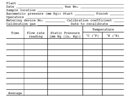
At least once
an hour, record the metering device flow rate or pressure drop reading, and the
metering device temperature and pressure. Make a minimum of 12 equally spaced
readings of each parameter during the test period. Record the barometric
pressure at the beginning and end of the test period. Record the data on a
table similar to that shown in Figure 2D-1.
8.2.2 Non-continuous and Non-steady Flow.
Use volume
rate devices with particular caution. Calibration will be affected by variation
in stack gas temperature, pressure and molecular weight. Use the procedure in
Section 8.2.1 with the addition of the following: Record all the metering
device parameters on a time interval frequency sufficient to adequately profile
each process cyclical or non-continuous event. A multi-channel continuous
recorder may be used.
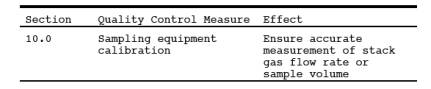
9.0 Quality Control.
10.0 Calibration and Standardization.
Same as Method 2A, Section 10.0, with the following
exception:
10.1 Gas Metering Device.
Same as Method
2A, Section 10.1, except calibrate the metering device with the principle stack
gas to be measured (examples: air, nitrogen) against a standard reference
meter. A calibrated dry gas meter is an acceptable reference meter. Ideally,
calibrate the metering device in the field with the actual gas to be metered.
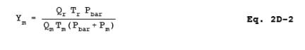
For metering devices that have a volume rate readout, calculate the test metering
device calibration coefficient, Ym,
for each run shown in Equation 2D-2 Section 12.3.
10.2 For metering devices that do not have a volume rate readout
Refer to the
manufacturer's instructions to calculate the Vm corresponding
to each Vr.
10.3 Temperature Gauge.
Use the
procedure and specifications in Method 2A,
Section 10.2. Perform the calibration at a temperature that approximates
field test conditions.
10.4 Barometer.
Calibrate the
barometer to be used in the field test with a mercury barometer prior to the
field test.
11.0 Analytical Procedure.
Sample
collection and analysis are concurrent for this method (see Section 8.0).
12.0 Data Analysis and Calculations.
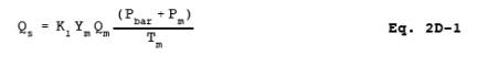
12.1 Nomenclature.
Pbar = Barometric pressure, mm Hg (in. Hg).
Pm = Test meter average static pressure, mm
Hg (in. Hg).
Qr = Reference meter volume flow rate
reading, m3/min (ft3/min).
Qm = Test meter volume flow rate reading, m3/min (ft3/min).
Tr = Absolute reference meter average
temperature, ˚K (˚R).
Tm= Absolute test meter average
temperature, ˚K (˚R).
K1 = 0.3855 ˚K/mm Hg for metric units,
= 17.65 ˚R/in.
Hg for English units.
12.2 Gas Flow Rate.
12.3 Test Meter Device Calibration Coefficient.
Calculation
for testing metering device calibration coefficient, Ym.
13.0 Method Performance. [Reserved]
14.0 Pollution Prevention. [Reserved]
15.0 Waste Management. [Reserved]
16.0 References.
1. Spink, L.K.
Principles and Practice of Flowmeter Engineering. The Foxboro Company. Foxboro,
MA. 1967.
2. Benedict,
R.P. Fundamentals of Temperature, Pressure, and Flow Measurements. John Wiley
& Sons, Inc. New York, NY. 1969.
3. Orifice
Metering of Natural Gas. American Gas Association. Arlington, VA. Report No. 3.
March 1978. 88 pp.
17.0 Tables, Diagrams, Flowcharts, and Validation Data.
Figure
2D-1. Volume flow rate measurement data.