METHOD
2A - DIRECT MEASUREMENT OF GAS VOLUME THROUGH PIPES AND SMALL DUCTS
NOTE: This method does not include all of the
specifications (e.g.,
equipment and supplies) and procedures (e.g., sampling) essential to its performance. Some
material is incorporated by reference from other methods in this part.
Therefore, to obtain reliable results, persons using this method should have a
thorough knowledge of at least the following additional test methods: Method 1,
Method 2.
7.0 Reagents and Standards.
[Reserved]
8.0 Sample Collection and
Analysis.
8.3.1 For sources with
continuous, steady emission flow rates
8.3.2 For sources with
noncontinuous, non-steady emission flow rates
10.0 Calibration and
Standardization.
12.0 Data Analysis and
Calculations.
12.2 Test Meter Calibration
Coefficient.
13.0 Method Performance.
[Reserved]
14.0 Pollution Prevention.
[Reserved]
15.0 Waste Management.
[Reserved]
17.0 Tables, Diagrams,
Flowcharts, and Validation Data. [Reserved]
1.0 Scope and Application.
1.1 This method is
applicable for the determination of gas flow rates in pipes and small ducts,
either in-line or at exhaust positions, within the temperature range of 0 to 50
°C (32 to 122 °F).
1.2 Data Quality
Objectives. Adherence to the requirements of this method will enhance the
quality of the data obtained from air pollutant sampling methods.
2.0 Summary of Method.
2.1 A gas volume
meter is used to measure gas volume directly. Temperature and pressure
measurements are made to allow correction of the volume to standard conditions.
3.0 Definitions. [Reserved]
4.0 Interferences. [Reserved]
5.0 Safety.
5.1 Disclaimer.
This method may
involve hazardous materials, operations, and equipment. This test method may
not address all of the safety problems associated with its use. It is the
responsibility of the user of this test method to establish appropriate safety
and health practices and determine the applicability of regulatory limitations
prior to performing this test method.
6.0 Equipment and Supplies.
Specifications for
the apparatus are given below. Any other apparatus that has been demonstrated
(subject to approval of the Administrator) to be capable of meeting the
specifications will be considered acceptable.
6.1 Gas Volume Meter.
A positive
displacement meter, turbine meter, or other direct measuring device capable of
measuring volume to within 2 percent. The meter shall be equipped with a
temperature sensor (accurate to within ±2 percent of the minimum absolute
temperature) and a pressure gauge (accurate to within ±2.5 mm Hg). The
manufacturer's recommended capacity of the meter shall be sufficient for the
expected maximum and minimum flow rates for the sampling conditions.
Temperature, pressure, corrosive characteristics, and pipe size are factors
necessary to consider in selecting a suitable gas meter.
6.2 Barometer.
A mercury, aneroid,
or other barometer capable of measuring atmospheric pressure to within ±2.5 mm
Hg.
NOTE: In many cases, the barometric reading may be
obtained from a nearby National Weather Service station, in which case the
station value (which is the absolute barometric pressure) shall be requested
and an adjustment for elevation differences between the weather station and
sampling point shall be applied at a rate of minus 2.5 mm (0.1 in.) Hg per 30 m
(100 ft) elevation increase or vice versa for elevation decrease.
6.3 Stopwatch.
Capable of
measurement to within 1 second.
7.0 Reagents and Standards. [Reserved]
8.0 Sample Collection and Analysis.
8.1 Installation.
As there are numerous
types of pipes and small ducts that may be subject to volume measurement, it
would be difficult to describe all possible installation schemes. In general,
flange fittings should be used for all connections wherever possible. Gaskets
or other seal materials should be used to assure leak-tight connections. The
volume meter should be located so as to avoid severe vibrations and other
factors that may affect the meter calibration.
8.2 Leak Test.
8.2.1 A volume meter
installed at a location under positive pressure may be leak-checked at the meter
connections by using a liquid leak detector solution containing a surfactant.
Apply a small amount of the solution to the connections. If a leak exists,
bubbles will form, and the leak must be corrected.
8.2.2 A volume meter
installed at a location under negative pressure is very difficult to test for
leaks without blocking flow at the inlet of the line and watching for meter
movement. If this procedure is not possible, visually check all connections to
assure leak-tight seals.
8.3 Volume Measurement.
8.3.1 For sources with continuous, steady emission flow rates
Record the initial
meter volume reading, meter temperature(s), meter pressure, and start the
stopwatch. Throughout the test period, record the meter temperatures and
pressures so that average values can be determined. At the end of the test,
stop the timer, and record the elapsed time, the final volume reading, meter
temperature, and pressure. Record the barometric pressure at the beginning and
end of the test run. Record the data on a table similar to that shown in Figure
2A-1.
8.3.2 For sources with noncontinuous, non-steady emission flow rates
Use the procedure in
Section 8.3.1 with the addition of the following: Record all the meter
parameters and the start and stop times corresponding to each process cyclical
or noncontinuous event.
9.0 Quality Control.
10.0 Calibration and Standardization.
10.1 Volume Meter.
10.1.1 The volume
meter is calibrated against a standard reference meter prior to its initial use
in the field. The reference meter is a spirometer or liquid displacement meter
with a capacity consistent with that of the test meter.
10.1.2 Alternatively,
a calibrated, standard pitot may be used as the reference meter in conjunction
with a wind tunnel assembly. Attach the test meter to the wind tunnel so that
the total flow passes through the test meter. For each calibration run, conduct
a 4-point traverse along one stack diameter at a position at least eight
diameters of straight tunnel downstream and two diameters upstream of any bend,
inlet, or air mover. Determine the traverse point locations as specified in
Method 1. Calculate the reference volume using the velocity values following
the procedure in Method 2, the wind tunnel cross-sectional area, and the run
time.
10.1.3 Set up the
test meter in a configuration similar to that used in the field installation (i.e., in relation to the flow moving device).
Connect the temperature sensor and pressure gauge as they are to be used in the
field. Connect the reference meter at the inlet of the flow line, if
appropriate for the meter, and begin gas flow through the system to condition
the meters. During this conditioning operation, check the system for leaks.
10.1.4 The
calibration shall be performed during at least three different flow rates. The
calibration flow rates shall be about 0.3, 0.6, and 0.9 times the rated maximum
flow rate of the test meter.
10.1.5 For each
calibration run, the data to be collected include: reference meter initial and
final volume readings, the test meter initial and final volume reading, meter
average temperature and pressure, barometric pressure, and run time. Repeat the
runs at each flow rate at least three times.
10.1.6 Calculate the test
meter calibration coefficient as indicated in Section 12.2.
10.1.7 Compare the
three Ym values at each of the flow rates tested and
determine the maximum and minimum values. The difference between the maximum
and minimum values at each flow rate should be no greater than 0.030. Extra
runs may be required to complete this requirement. If this specification cannot
be met in six successive runs, the test meter is not suitable for use. In
addition, the meter coefficients should be between 0.95 and 1.05. If these
specifications are met at all the flow rates, average all the Ym values from runs meeting the specifications to obtain an average
meter calibration coefficient, Ym.
10.1.8 The procedure
above shall be performed at least once for each volume meter. Thereafter, an
abbreviated calibration check shall be completed following each field test. The
calibration of the volume meter shall be checked with the meter pressure set at
the average value encountered during the field test. Three calibration checks (runs)
shall be performed using this average flow rate value. Calculate the average
value of the calibration factor. If the calibration has changed by more than 5
percent, recalibrate the meter over the full range of flow as described above.
NOTE: If the volume meter calibration coefficient
values obtained before and after a test series differ by more than 5 percent,
the test series shall either be voided, or calculations for the test series
shall be performed using whichever meter coefficient value (i.e., before or after) gives the greater value of
pollutant emission rate.
10.2 Temperature Sensor.
After each test
series, check the temperature sensor at ambient temperature. Use an American
Society for Testing and Materials (ASTM) mercury in-glass reference thermometer,
or equivalent, as a reference. If the sensor being checked agrees within 2
percent (absolute temperature) of the reference, the temperature data collected
in the field shall be considered valid. Otherwise, the test data shall be
considered invalid or adjustments of the results shall be made, subject to the
approval of the Administrator.
10.3 Barometer.
Calibrate the
barometer used against a mercury barometer prior to the field test.
11.0 Analytical Procedure.
Sample collection and
analysis are concurrent for this method (see Section 8.0).
12.0 Data Analysis and Calculations.
Carry out
calculations, retaining at least one extra decimal figure beyond that of the
acquired data. Round off figures after final calculation.
12.1 Nomenclature.
f = Final reading.
i = Initial reading.
Pbar = Barometric pressure, mm Hg.
Pg = Average static pressure in volume meter, mm Hg.
Qs = Gas flow rate, m3/min, standard
conditions.
s = Standard
conditions, 20°C and 760 mm Hg.
Tr = Reference meter average temperature, °K (°R).
Tm = Test meter average temperature, °K (°R).
Vr = Reference meter volume reading, m3.
Vm = Test meter volume reading, m3.
Ym = Test meter calibration coefficient, dimensionless.
•
= Elapsed test period time, min.
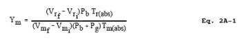
12.2 Test Meter Calibration Coefficient.
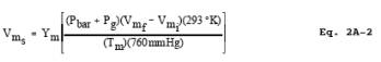
12.3 Volume.
12.4 Gas Flow Rate.
![]()
13.0 Method Performance. [Reserved]
14.0 Pollution Prevention. [Reserved]
15.0 Waste Management. [Reserved]
16.0 References.
1. Rom, Jerome J. Maintenance,
Calibration, and Operation of Isokinetic Source Sampling Equipment. U.S.
Environmental Protection Agency, Research Triangle Park, NC. Publication No.
APTD-0576. March 1972.
2. Wortman, Martin,
R. Vollaro, and P.R. Westlin. Dry Gas Volume Meter Calibrations. Source
Evaluation Society Newsletter. Vol. 2, No. 2. May 1977.
3. Westlin, P.R., and
R.T. Shigehara. Procedure for Calibrating and Using Dry Gas Volume Meters as
Calibration Standards. Source Evaluation Society Newsletter. Vol. 3, No. 1. February
1978.
17.0 Tables, Diagrams, Flowcharts, and Validation Data. [Reserved]