METHOD 2C -
DETERMINATION OF GAS VELOCITY AND VOLUMETRIC FLOW RATE IN SMALL STACKS OR DUCTS
(STANDARD PITOT TUBE)
NOTE: This method does not include all of the
specifications (e.g.,
equipment and supplies) and procedures (e.g., sampling) essential to its performance.
Some material is incorporated by reference from other methods in this part.
Therefore, to obtain reliable results, persons using this method should also
have a thorough knowledge of at least the following additional test methods: Method 1, Method 2.
6.1 Standard Pitot Tube
(instead of Type S).
7.0 Reagents and Standards.
[Reserved]
8.0 Sample Collection and
Analysis.
10.0 Calibration and
Standardization.
12.0 Calculations and Data
Analysis.
13.0 Method Performance.
[Reserved]
14.0 Pollution Prevention.
[Reserved]
15.0 Waste Management.
[Reserved]
17.0 Tables, Diagrams,
Flowcharts, and Validation Data.
1.0 Scope and Application.
1.1 This
method is applicable for the determination of average velocity and volumetric
flow rate of gas streams in small stacks or ducts. Limits on the applicability
of this method are identical to those set forth in Method 2, Section 1.0,
except that this method is limited to stationary source stacks or ducts less
than about 0.30 meter (12 in.) in diameter, or 0.071 m2 (113 in.2)
in cross-sectional area, but equal to or greater than about 0.10 meter (4 in.)
in diameter, or 0.0081 m2
(12.57 in.2) in cross-sectional area.
1.2 Data
Quality Objectives. Adherence to the requirements of this method will enhance
the quality of the data obtained from air pollutant sampling methods.
2.0 Summary of Method.
2.1 The
average gas velocity in a stack or duct is determined from the gas density and
from measurement of velocity heads with a standard pitot tube.
3.0 Definitions. [Reserved]
4.0 Interferences. [Reserved]
5.0 Safety.
5.1 This
method may involve hazardous materials, operations, and equipment. This test
method may not address all of the safety problems associated with its use. It is
the responsibility of the user of this test method to establish appropriate
safety and health practices and determine the applicability of regulatory
limitations prior to performing this test method.
6.0 Equipment and Supplies.
Same as Method 2, Section 6.0, with the exception of the
following:
6.1 Standard Pitot Tube (instead of Type S).
A standard
pitot tube which meets the specifications of Section
6.7 of Method 2. Use a coefficient of O.99 unless it is calibrated against
another standard pitot tube with a NIST-traceable coefficient (see Section 10.2 of Method 2).
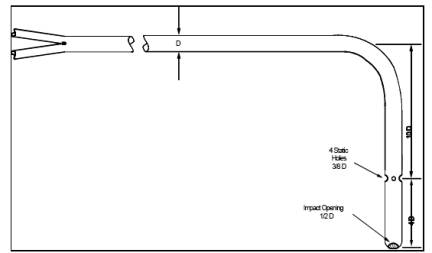
6.2 Alternative Pitot Tube.
A modified
hemispherical-nosed pitot tube (see Figure 2C-1), which
features a shortened stem and enlarged impact and static pressure holes. Use a
coefficient of 0.99 unless it is calibrated as mentioned in Section 6.1 above.
This pitot tube is useful in particulate liquid droplet-laden gas streams when
a "back purge" is ineffective.
7.0 Reagents and Standards. [Reserved]
8.0 Sample Collection and Analysis.
8.1 Follow the
general procedures in Section 8.0 of Method 2,
except conduct the measurements at the traverse points specified in Method 1A. The static and impact pressure holes of
standard pitot tubes are susceptible to plugging in particulate-laden gas
streams. Therefore, adequate proof that the openings of the pitot tube have not
plugged during the traverse period must be furnished; this can be done by
taking the velocity head (•p) heading at the final traverse point, cleaning out
the impact and static holes of the standard pitot tube by
"back-purging" with pressurized air, and then taking another •p
reading. If the •p readings made before and after the air purge are the same
(within ±5 percent) the traverse is acceptable. Otherwise, reject the run. Note
that if the •p at the final traverse point is unsuitably low, another point may
be selected. If "back purging" at regular intervals is part of the
procedure, then take comparative •p readings, as above, for the last two back
purges at which suitably high •p readings are observed.
9.0 Quality Control.
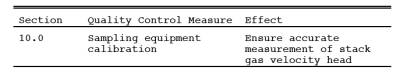
10.0 Calibration and Standardization.
Same as Method
2, Sections 10.2 through 10.4.
11.0 Analytical Procedure.
Sample
collection and analysis are concurrent for this method (see Section 8.0).
12.0 Calculations and Data Analysis.
Same as Method
2, Section 12.0.
13.0 Method Performance. [Reserved]
14.0 Pollution Prevention. [Reserved]
15.0 Waste Management. [Reserved]
16.0 References.
Same as Method
2, Section 16.0.
17.0 Tables, Diagrams, Flowcharts, and Validation Data.
Figure
2C-1. Modified Hemispherical-Nosed Pitot Tube.