METHOD
1A - SAMPLE AND VELOCITY TRAVERSES FOR STATIONARYSOURCES WITH SMALL STACKS OR
DUCTS
NOTE: This method does not include all of the
specifications (e.g.,
equipment and supplies) and procedures (e.g., sampling) essential to its performance.
Some material is incorporated by reference from other methods in this part.
Therefore, to obtain reliable results, persons using this method should have a
thorough knowledge of at least the following additional test method: Method 1.
6.0 Equipment and Supplies.
[Reserved]
7.0 Reagents and Standards.
[Reserved]
8.0 Sample Collection,
Preservation, Storage, and Transport. [Reserved]
9.0 Quality Control.
[Reserved]
10.0 Calibration and
Standardization. [Reserved]
11.1 Selection of Measurement
Site.
11.1.1 Particulate
Measurements –
11.1.2 PM Sampling (Steady
Flow) or Velocity (Steady or Unsteady Flow)
11.2 Determining the Number of
Traverse Points.
11.2.1 Particulate
Measurements (Steady or Unsteady Flow).
11.2.2 PM Sampling (Steady
Flow) or only Velocity (Non-Particulate) Measurements.
12.0 Data Analysis and
Calculations. [Reserved]
13.0 Method Performance.
[Reserved]
14.0 Pollution Prevention.
[Reserved]
15.0 Waste Management.
[Reserved]
17.0 Tables, Diagrams,
Flowcharts, and Validation Data.
1.0 Scope and Application.
1.1 Measured Parameters.
The purpose of the
method is to provide guidance for the selection of sampling ports and traverse
points at which sampling for air pollutants will be performed pursuant to
regulations set forth in this part.
1.2 Applicability.
The applicability
and principle of this method are identical to Method 1, except its
applicability is limited to stacks or ducts. This method is applicable to
flowing gas streams in ducts, stacks, and flues of less than about O.30 meter
(12 in.) in diameter, or 0.071 m2 (113 in.2) in cross-sectional area, but equal to or
greater than about O.10 meter (4 in.) in diameter, or 0.0081 m2 (12.57 in.2) in
cross-sectional area. This method cannot be used when the flow is cyclonic or
swirling.
1.3 Data Quality Objectives.
Adherence to the
requirements of this method will enhance the quality of the data obtained from
air pollutant sampling methods.
2.0 Summary of Method.
2.1 The method is
designed to aid in the representative measurement of pollutant emissions and/or
total volumetric flow rate from a stationary source. A measurement site or a
pair of measurement sites where the effluent stream is flowing in a known
direction is (are) selected. The cross-section of the stack is divided into a
number of equal areas. Traverse points are then located within each of these
equal areas.
2.2 In these small
diameter stacks or ducts, the conventional Method 5
stack assembly (consisting of a Type S pitot tube attached to a sampling probe,
equipped with a nozzle and thermocouple) blocks a significant portion of the
cross-section of the duct and causes inaccurate measurements. Therefore, for
particulate matter (PM) sampling in small stacks or ducts, the gas velocity is
measured using a standard pitot tube downstream of the actual emission sampling
site. The straight run of duct between the PM sampling and velocity measurement
sites allows the flow profile, temporarily disturbed by the presence of the
sampling probe, to redevelop and stabilize.
3.0 Definitions. [Reserved]
4.0 Interferences. [Reserved]
5.0 Safety.
5.1 Disclaimer.
This method may
involve hazardous materials, operations, and equipment. This test method may
not address all of the safety problems associated with its use. It is the
responsibility of the user of this test method to establish appropriate safety
and health practices and determine the applicability of regulatory limitations
prior to performing this test method.
6.0 Equipment and Supplies. [Reserved]
7.0 Reagents and Standards. [Reserved]
8.0 Sample Collection, Preservation, Storage, and Transport. [Reserved]
9.0 Quality Control. [Reserved]
10.0 Calibration and Standardization. [Reserved]
11.0 Procedure.
11.1 Selection of Measurement Site.
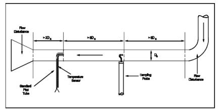
11.1.1 Particulate Measurements –
Steady or Unsteady
Flow. Select a particulate measurement site located preferably at least eight
equivalent stack or duct diameters downstream and 10 equivalent diameters
upstream from any flow disturbances such as bends, expansions, or contractions
in the stack, or from a visible flame. Next, locate the velocity measurement
site eight equivalent diameters downstream of the particulate measurement site
(see Figure 1A-1). If such locations are not available,
select an alternative particulate measurement location at least two equivalent
stack or duct diameters downstream and two and one-half diameters upstream from
any flow disturbance. Then, locate the velocity measurement site two equivalent
diameters downstream from the particulate measurement site. (See Section 12.2 of Method 1 for calculating
equivalent diameters for a rectangular cross-section.)
11.1.2 PM Sampling (Steady Flow) or Velocity (Steady or Unsteady Flow)
Measurements. For
PM sampling when the volumetric flow rate in a duct is constant with respect to
time, Section 11.1.1 of Method 1 may be
followed, with the PM sampling and velocity measurement performed at one
location. To demonstrate that the flow rate is constant (within 10 percent)
when PM measurements are made, perform complete velocity traverses before and
after the PM sampling run, and calculate the deviation of the flow rate derived
after the PM sampling run from the one derived before the PM sampling run. The
PM sampling run is acceptable if the deviation does not exceed 10 percent.
11.2 Determining the Number of Traverse Points.
11.2.1 Particulate Measurements (Steady or Unsteady Flow).
Use Figure 1-1 of Method 1 to determine the number of
traverse points to use at both the velocity measurement and PM sampling
locations. Before referring to the figure, however, determine the distances
between both the velocity measurement and PM sampling sites to the nearest
upstream and downstream disturbances. Then divide each distance by the stack
diameter or equivalent diameter to express the distances in terms of the number
of duct diameters. Then, determine the number of traverse points from Figure
1-1 of Method 1 corresponding to each of these four distances. Choose the
highest of the four numbers of traverse points (or a greater number) so that,
for circular ducts the number is a multiple of four; and for rectangular ducts,
the number is one of those shown in Table 1-1 of
Method 1. When the optimum duct diameter location criteria can be satisfied,
the minimum number of traverse points required is eight for circular ducts and
nine for rectangular ducts.
11.2.2 PM Sampling (Steady Flow) or only Velocity (Non-Particulate) Measurements.
Use Figure 1-2 of Method 1 to determine number of
traverse points, following the same procedure used for PM sampling as described
in Section 11.2.1 of Method 1. When the optimum duct diameter location criteria
can be satisfied, the minimum number of traverse points required is eight for
circular ducts and nine for rectangular ducts.
11.3 Cross-sectional Layout, Location of Traverse Points, and Verification of the Absence of Cyclonic Flow.
Same as Method 1,
Sections 11.3 and 11.4, respectively.
12.0 Data Analysis and Calculations. [Reserved]
13.0 Method Performance. [Reserved]
14.0 Pollution Prevention. [Reserved]
15.0 Waste Management. [Reserved]
16.0 References.
Same as Method 1, Section 16.0, References 1 through 6, with
the addition of the following:
1. Vollaro, Robert
F. Recommended Procedure for Sample Traverses in Ducts Smaller Than 12 Inches
in Diameter. U.S. Environmental Protection Agency, Emission Measurement Branch,
Research Triangle Park, North Carolina. January 1977.
17.0 Tables, Diagrams, Flowcharts, and Validation Data.
Figure
1A-1. Recommended sampling arrangement for small ducts