METHOD
26A - DETERMINATION OF HYDROGEN HALIDE AND HALOGEN EMISSIONS FROM STATIONARY
SOURCES ISOKINETIC METHOD
NOTE: This method does not include all of the
specifications (e.g. equipment
and supplies) and procedures (e.g. sampling
and analytical) essential to its performance. Some material is incorporated by
reference from other methods in this part. Therefore, to obtain reliable
results, persons using this method should have a thorough knowledge of at least
the following additional test methods: Method 2, Method 5, and Method 26.
6.1.4 Cyclone
(Optional). Glass or Teflon.
6.1.8 Ambient Air
Conditioning Tube (Optional).
6.3 Sample Preparation
and Analysis.
7.2 Sample Preparation
and Analysis.
7.3 Quality Assurance
Audit Samples.
8.0 Sample Collection,
Preservation, Storage, and Transport.
8.1.2 Preliminary
Determinations.
8.1.3 Preparation of
Sampling Train.
8.1.5 Sampling Train
Operation.
8.1.6 Post-Test
Moisture Removal (Optional).
8.2.1 Container No. 1
(Optional; Filter Catch for Particulate Determination).
8.2.2 Container No. 2
(Optional; Front-Half Rinse for Particulate Determination).
8.2.4 Container No. 4
(Alkaline Impinger Catch for Halogen and Moisture Determination).
8.2.5 Container No. 5
(Silica Gel for Moisture Determination).
8.2.6 Container Nos. 6
through 9 (Reagent Blanks).
10.0 Calibration and
Standardization.
11.2 Container Nos. 1
and 2 and Acetone Blank (Optional; Particulate Determination).
12.0. Data Analysis and
Calculations.
14.0 Pollution
Prevention. [Reserved]
15.0 Waste Management.
[Reserved]
17.0 Tables, Diagrams,
Flowcharts, and Validation Data.
1.0 Scope and Application.
1.1 Analytes.
1.2 This method is
applicable for determining emissions of hydrogen halides (HX) [HCl, HBr, and
HF] and halogens (X2) [Cl2 and Br2] from stationary sources when specified by the applicable subpart.
This method collects the emission sample isokinetically and is therefore
particularly suited for sampling at sources, such as those controlled by wet
scrubbers, emitting acid particulate matter (e.g., hydrogen halides dissolved
in water droplets).
1.3 Data Quality
Objectives. Adherence to the requirements of this method will enhance the
quality of the data obtained from air pollutant sampling methods.
2.0 Summary of Method.
2.1 Principle.
Gaseous and
particulate pollutants are withdrawn isokinetically from the source and
collected in an optional cyclone, on a filter, and in absorbing solutions. The
cyclone collects any liquid droplets and is not necessary if the source
emissions do not contain them; however, it is preferable to include the cyclone
in the sampling train to protect the filter from any liquid present. The filter
collects particulate matter including halide salts but is not routinely
recovered or analyzed. Acidic and alkaline absorbing solutions collect the
gaseous hydrogen halides and halogens, respectively. Following sampling of
emissions containing liquid droplets, any halides/halogens dissolved in the
liquid in the cyclone and on the filter are vaporized to gas and collected in
the impingers by pulling conditioned ambient air through the sampling train.
The hydrogen halides are solubilized in the acidic solution and form chloride
(Cl-), bromide (Br-),
and fluoride (F-) ions. The halogens have a very low solubility
in the acidic solution and pass through to the alkaline solution where they are
hydrolyzed to form a proton (H+), the halide ion, and
the hypohalous acid (HClO or HBrO). Sodium thiosulfate is added to the alkaline
solution to assure reaction with the hypohalous acid to form a second halide
ion such that 2 halide ions are formed for each molecule of halogen gas. The
halide ions in the separate solutions are measured by ion chromatography (IC).
If desired, the particulate matter recovered from the filter and the probe is
analyzed following the procedures in Method 5.
NOTE: If the tester intends to use this sampling
arrangement to sample concurrently for particulate matter, the alternative Teflon
probe liner, cyclone, and filter holder should not be used. The Teflon filter
support must be used. The tester must also meet the probe and filter
temperature requirements of both sampling trains.
3.0 Definitions. [Reserved]
4.0 Interferences.
4.1 Volatile
materials, such as chlorine dioxide (ClO2) and
ammonium chloride (NH4Cl), which produce halide ions upon dissolution
during sampling are potential interferents. Interferents for the halide
measurements are the halogen gases which disproportionate to a hydrogen halide
and a hypohalous acid upon dissolution in water. The use of acidic rather than
neutral or basic solutions for collection of the hydrogen halides greatly
reduces the dissolution of any halogens passing through this solution.
4.2 The simultaneous
presence of both HBr and Cl2 may cause a positive
bias in the HCl result with a corresponding negative bias in the Cl2 result as well as affecting the HBr/Br2 split.
4.3 High
concentrations of nitrogen oxides (NOx) may produce
sufficient nitrate (NO3-) to interfere with measurements of very low Br- levels.
4.4 There is
anecdotal evidence that HF may be outgassed from new Teflon components. If HF
is a target analyte then preconditioning of new Teflon components, by heating,
should be considered.
5.0 Safety.
5.1 Disclaimer.
This method may
involve hazardous materials, operations, and equipment. This test method may
not address all of the safety problems associated with its use. It is the
responsibility of the user to establish appropriate safety and health practices
and determine the applicability of regulatory limitations before performing
this test method.
5.2 Corrosive Reagents.
The following
reagents are hazardous. Personal protective equipment and safe procedures are
useful in preventing chemical splashes. If contact occurs, immediately flush
with copious amounts of water for at least 15 minutes. Remove clothing under
shower and decontaminate. Treat residual chemical burns as thermal burns.
5.2.1 Sodium
Hydroxide (NaOH). Causes severe damage to eyes and skin. Inhalation causes
irritation to nose, throat, and lungs. Reacts exothermically with limited
amounts of water.
5.2.2 Sulfuric Acid
(H2SO4). Rapidly
destructive to body tissue. Will cause third degree burns. Eye damage may
result in blindness. Inhalation may be fatal from spasm of the larynx, usually
within 30 minutes. May cause lung tissue damage with edema. 1 mg/m3 for 8 hours will cause lung damage or, in higher concentrations,
death. Provide ventilation to limit inhalation. Reacts violently with metals
and organics.
6.0. Equipment and Supplies.
NOTE: Mention of trade names or specific products does
not constitute endorsement by the Environmental Protection Agency.
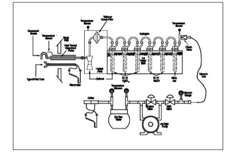
6.1 Sampling.
The sampling train is
shown in Figure 26A-1; the apparatus is similar to the
Method 5 train where noted as follows:
6.1.1 Probe Nozzle.
Borosilicate or
quartz glass; constructed and calibrated according to Method 5, Sections 6.1.1.1
and 10.1, and coupled to the probe liner
using a Teflon union; a stainless steel nut is recommended for this union. When
the stack temperature exceeds 210˚C (410˚F), a one-piece glass nozzle/liner
assembly must be used.
6.1.2 Probe Liner.
Same as Method 5,
Section 6.1.1.2, except metal liners shall not be used. Watercooling of the
stainless steel sheath is recommended at temperatures exceeding 500˚C (932˚F).
Teflon may be used in limited applications where the minimum stack temperature
exceeds 120˚C (250˚F) but never exceeds the temperature where Teflon is
estimated to become unstable [approximately 210˚C (410˚F)].
6.1.3 Pitot Tube, Differential Pressure Gauge, Filter Heating System, Metering System, Barometer, Gas Density Determination Equipment.
Same as Method 5,
Sections 6.1.1.3, 6.1.1.4, 6.1.1.6, 6.1.1.9, 6.1.2, and 6.1.3.
6.1.4 Cyclone (Optional). Glass or Teflon.
Use of the cyclone is
required only when the sample gas stream is saturated with moisture; however,
the cyclone is recommended to protect the filter from any liquid droplets
present.
6.1.5 Filter Holder.
Borosilicate or
quartz glass, or Teflon filter holder, with a Teflon filter support and a
sealing gasket. The sealing gasket shall be constructed of Teflon or equivalent
materials. The holder design shall provide a positive seal against leakage at
any point along the filter circumference. The holder shall be attached
immediately to the outlet of the cyclone.
6.1.6 Impinger Train.
The following system
shall be used to determine the stack gas moisture content and to collect the
hydrogen halides and halogens: five or six impingers connected in series with
leak-free ground glass fittings or any similar leak-free noncontaminating
fittings. The first impinger shown in Figure 26A-1 (knockout or condensate
impinger) is optional and is recommended as a water knockout trap for use under
high moisture conditions. If used, this impinger should be constructed as
described below for the alkaline impingers, but with a shortened stem, and
should contain 50 ml of 0.1 N H2SO4. The following two impingers (acid impingers
which each contain 100 ml of 0.1 N H2SO4) shall be of the Greenburg-Smith design with the standard tip
(Method 5, Section 6.1.1.8). The next two impingers (alkaline impingers which
each contain 100 ml of 0.1 N NaOH) and the last impinger (containing silica gel)
shall be of the modified Greenburg-Smith design (Method 5, Section 6.1.1.8).
The condensate, acid, and alkaline impingers shall contain known quantities of
the appropriate absorbing reagents. The last impinger shall contain a known
weight of silica gel or equivalent desiccant. Teflon impingers are an
acceptable alternative.
6.1.7 Heating System.
Any heating system
capable of maintaining a temperature around the probe and filter holder greater
than 120 ˚C (248 ˚F) during sampling, or such other temperature as specified by
an applicable subpart of the standards or approved by the Administrator for a
particular application.
6.1.8 Ambient Air Conditioning Tube (Optional).
Tube tightly packed
with approximately 150 g of fresh 8 to 20 mesh sodium hydroxide-coated silica,
or equivalent, (Ascarite II has been found suitable) to dry and remove acid
gases from the ambient air used to remove moisture from the filter and cyclone,
when the cyclone is used. The inlet and outlet ends of the tube should be
packed with at least 1-cm thickness of glass wool or filter material suitable
to prevent escape of fines. Fit one end with flexible tubing, etc. to allow
connection to probe nozzle following the test run.
6.2 Sample Recovery.
6.2.1 Probe-Liner and
Probe-Nozzle Brushes, Wash Bottles, Glass Sample Storage Containers, Petri
Dishes, Graduated Cylinder and/or Balance, and Rubber Policeman. Same as Method 5, Sections 6.2.1, 6.2.2, 6.2.3, 6.2.4,
6.2.5, and 6.2.7.
6.2.2 Plastic Storage
Containers. Screw-cap polypropylene or polyethylene containers to store silica
gel. High-density polyethylene bottles with Teflon screw cap liners to store
impinger reagents, 1-liter.
6.2.3 Funnels. Glass
or high-density polyethylene, to aid in sample recovery.
6.3 Sample Preparation and Analysis.
6.3.1 Volumetric
Flasks. Class A, various sizes.
6.3.2 Volumetric
Pipettes. Class A, assortment. To dilute samples to calibration range of the
ion chromatograph (IC).
6.3.3 Ion
Chromatograph (IC). Suppressed or non-suppressed, with a conductivity detector
and electronic integrator operating in the peak area mode. Other detectors, a
strip chart recorder, and peak heights may be used.
7.0 Reagents and Standards.
NOTE: Unless otherwise indicated, all reagents must
conform to the specifications established by the Committee on Analytical
Reagents of the American Chemical Society (ACS reagent grade). When such
specifications are not available, the best available grade shall be used.
7.1 Sampling.
7.1.1 Filter. Teflon
mat (e.g., Pallflex TX40HI45) filter. When the stack gas temperature exceeds
210˚C (410˚F) a quartz fiber filter may be used.
7.1.2 Water.
Deionized, distilled water that conforms to American Society of Testing and
Materials (ASTM) Specification D 1193-77 or 91, Type 3 (incorporated by
reference - see § 60.17).
7.1.3 Acidic
Absorbing Solution, 0.1 N Sulfuric Acid (H2SO4). To prepare 1 L, slowly add 2.80 ml of concentrated 17.9 M H2SO4 to about 900 ml of water while stirring, and
adjust the final volume to 1 L using additional water. Shake well to mix the
solution.
7.1.4 Silica Gel,
Crushed Ice, and Stopcock Grease. Same as Method
5, Sections 7.1.2, 7.1.4, and 7.1.5, respectively.
7.1.5 Alkaline
Absorbing Solution, 0.1 N Sodium Hydroxide (NaOH). To prepare 1 L, dissolve
4.00 g of solid NaOH in about 900 ml of water and adjust the final volume to 1
L using additional water. Shake well to mix the solution.
7.1.6 Sodium
Thiosulfate, (Na2S2O33.5 H2O).
7.2 Sample Preparation and Analysis.
7.2.1 Water. Same as
in Section 7.1.2.
7.2.2 Absorbing
Solution Blanks. A separate blank solution of each absorbing reagent should be
prepared for analysis with the field samples. Dilute 200 ml of each absorbing
solution (250 ml of the acidic absorbing solution, if a condensate impinger is
used) to the same final volume as the field samples using the blank sample of
rinse water. If a particulate determination is conducted, collect a blank
sample of acetone.
7.2.3 Halide Salt
Stock Standard Solutions. Prepare concentrated stock solutions from reagent
grade sodium chloride (NaCl), sodium bromide (NaBr), and sodium fluoride (NaF).
Each must be dried at 110˚C (230˚F) for two or more hours and then cooled to
room temperature in a desiccator immediately before weighing. Accurately weigh
1.6 to 1.7 g of the dried NaCl to within 0.1 mg, dissolve in water, and dilute
to 1 liter. Calculate the exact Cl- concentration
using Equation 26A-1 in Section 12.2. In a similar
manner, accurately weigh and solubilize 1.2 to 1.3 g of dried NaBr and 2.2 to
2.3 g of NaF to make 1-liter solutions. Use Equations 26A-2 and 26A-3 in
Section 12.2, to calculate the Br- and F- concentrations. Alternately, solutions containing a nominal
certified concentration of 1000 mg/L NaCl are commercially available as
convenient stock solutions from which standards can be made by appropriate
volumetric dilution. Refrigerate the stock standard solutions and store no
longer than one month.
7.2.4 Chromatographic
Eluent. Same as Method 26, Section 7.2.4.
7.2.5 Water. Same as
Section 7.1.1.
7.2.6 Acetone. Same
as Method 5, Section 7.2.
7.3 Quality Assurance Audit Samples.
When making
compliance determinations, and upon availability, audit samples may be obtained
from the appropriate EPA regional Office or from the responsible enforcement
authority.
NOTE: The responsible enforcement authority should be
notified at least 30 days prior to the test date to allow sufficient time for
sample delivery.
8.0 Sample Collection, Preservation, Storage, and Transport.
NOTE: Because of the complexity of this method,
testers and analysts should be trained and experienced with the procedures to
ensure reliable results.
8.1 Sampling.
8.1.1 Pretest Preparation.
Follow the general
procedure given in Method 5, Section 8.1,
except the filter need only be desiccated and weighed if a particulate
determination will be conducted.
8.1.2 Preliminary Determinations.
Same as Method 5, Section 8.2.
8.1.3 Preparation of Sampling Train.
Follow the general
procedure given in Method 5, Section 8.1.3, except for the following
variations: Add 50 ml of 0.1 N H2SO4 to the condensate impinger, if used. Place 100 ml of 0.1 N H2SO4 in each of the next two impingers. Place 100 ml
of 0.1 N NaOH in each of the following two impingers. Finally, transfer
approximately 200-300 g of preweighed silica gel from its container to the last
impinger. Set up the train as in Figure 26A-1. When
used, the optional cyclone is inserted between the probe liner and filter
holder and located in the heated filter box.
8.1.4 Leak-Check Procedures.
Follow the leak-check
procedures given in Method 5, Sections 8.4.2
(Pretest Leak- Check), 8.4.3 (Leak-Checks During the Sample Run), and 8.4.4
(Post-Test Leak-Check).
8.1.5 Sampling Train Operation.
Follow the general
procedure given in Method 5, Section 8.5. It
is important to maintain a temperature around the probe, filter (and cyclone,
if used) of greater than 120˚C (248 ˚F) since it is extremely difficult to
purge acid gases off these components. (These components are not quantitatively
recovered and hence any collection of acid gases on these components would result
in potential undereporting these emissions. The applicable subparts may specify
alternative higher temperatures.) For each run, record the data required on a
data sheet such as the one shown in Method 5, Figure
5-3. If the condensate impinger becomes too full, it may be emptied,
recharged with 50 ml of 0.1 N H2SO4, and replaced during the sample run. The condensate emptied must
be saved and included in the measurement of the volume of moisture collected
and included in the sample for analysis. The additional 50 ml of absorbing
reagent must also be considered in calculating the moisture. Before the
sampling train integrity is compromised by removing the impinger, conduct a
leak-check as described in Method 5, Section 8.4.2.
8.1.6 Post-Test Moisture Removal (Optional).
When the optional
cyclone is included in the sampling train or when liquid is visible on the
filter at the end of a sample run even in the absence of a cyclone, perform the
following procedure. Upon completion of the test run, connect the ambient air
conditioning tube at the probe inlet and operate the train with the filter
heating system at least 120˚C (248 ˚F) at a low flow rate (e.g., •H = 1 in. H2O) to vaporize any liquid and hydrogen halides in the cyclone or on
the filter and pull them through the train into the impingers. After 30
minutes, turn off the flow, remove the conditioning tube, and examine the
cyclone and filter for any visible liquid. If liquid is visible, repeat this
step for 15 minutes and observe again. Keep repeating until the cyclone is dry.
NOTE: It is critical that this is repeated until the
cyclone is completely dry.
8.2 Sample Recovery.
Allow the probe to
cool. When the probe can be handled safely, wipe off all the external surfaces
of the tip of the probe nozzle and place a cap loosely over the tip to prevent
gaining or losing particulate matter. Do not cap the probe tip tightly while
the sampling train is cooling down because this will create a vacuum in the
filter holder, drawing water from the impingers into the holder. Before moving
the sampling train to the cleanup site, remove the probe from the sample train,
wipe off any silicone grease, and cap the open outlet of the impinger train,
being careful not to lose any condensate that might be present. Wipe off any
silicone grease and cap the filter or cyclone inlet. Remove the umbilical cord
from the last impinger and cap the impinger. If a flexible line is used between
the first impinger and the filter holder, disconnect it at the filter holder
and let any condensed water drain into the first impinger. Wipe off any
silicone grease and cap the filter holder outlet and the impinger inlet. Ground
glass stoppers, plastic caps, serum caps, Teflon tape, Parafilm, or aluminum
foil may be used to close these openings. Transfer the probe and
filter/impinger assembly to the cleanup area. This area should be clean and
protected from the weather to minimize sample contamination or loss. Inspect
the train prior to and during disassembly and note any abnormal conditions.
Treat samples as follows:
8.2.1 Container No. 1 (Optional; Filter Catch for Particulate Determination).
Same as Method 5, Section 8.7.6.1, Container No. 1.
8.2.2 Container No. 2 (Optional; Front-Half Rinse for Particulate Determination).
Same as Method 5,
Section 8.7.6.2, Container No. 2.
8.2.3 Container No. 3 (Knockout and Acid Impinger Catch for Moisture and Hydrogen Halide Determination).
Disconnect the
impingers. Measure the liquid in the acid and knockout impingers to +1 ml by
using a graduated cylinder or by weighing it to +0.5 g by using a balance.
Record the volume or weight of liquid present. This information is required to
calculate the moisture content of the effluent gas. Quantitatively transfer
this liquid to a leak-free sample storage container. Rinse these impingers and
connecting glassware including the back portion of the filter holder (and
flexible tubing, if used) with water and add these rinses to the storage container.
Seal the container, shake to mix, and label. The fluid level should be marked
so that if any sample is lost during transport, a correction proportional to
the lost volume can be applied. Retain rinse water and acidic absorbing
solution blanks to be analyzed with the samples.
8.2.4 Container No. 4 (Alkaline Impinger Catch for Halogen and Moisture Determination).
Measure and record
the liquid in the alkaline impingers as described in Section 8.2.3.
Quantitatively transfer this liquid to a leak-free sample storage container.
Rinse these two impingers and connecting glassware with water and add these
rinses to the container. Add 25 mg of sodium thiosulfate per ppm halogen
anticipated to be in the stack gas multiplied by the volume (dscm) of stack gas
sampled (0.7 mg/ppm-dscf). Seal the container, shake to mix, and label; mark
the fluid level. Retain alkaline absorbing solution blank to be analyzed with
the samples.
NOTE: 25 mg per sodium thiosulfate per ppm halogen
anticipated to be in the stack includes a safety factor of approximately 5 to
assure complete reaction with the hypohalous acid to form a second Cl- ion in the alkaline solution.
8.2.5 Container No. 5 (Silica Gel for Moisture Determination).
Same as Method 5,
Section 8.7.6.3, Container No. 3.
8.2.6 Container Nos. 6 through 9 (Reagent Blanks).
Save portions of the
absorbing reagents (0.1 N H2SO4 and 0.1 N NaOH) equivalent to the amount used in the sampling
train; dilute to the approximate volume of the corresponding samples using
rinse water directly from the wash bottle being used. Add the same ratio of
sodium thiosulfate solution used in container No. 4 to the 0.1 N NaOH absorbing
reagent blank. Also, save a portion of the rinse water alone and a portion of
the acetone equivalent to the amount used to rinse the front half of the
sampling train. Place each in a separate, pre-labeled sample container.
8.2.7 Prior to shipment
Prior to shipment,
recheck all sample containers to ensure that the caps are well-secured. Seal
the lids of all containers around the circumference with Teflon tape. Ship all
liquid samples upright and all particulate filters with the particulate catch
facing upward.
9.0 Quality Control.
9.1 Miscellaneous
Quality Control Measures.
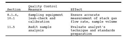
9.1 Volume Metering
System Checks. Same as Method 5, Section 9.2.
10.0 Calibration and Standardization.
NOTE: Maintain a laboratory log of all calibrations.
10.1 Probe Nozzle, Pitot Tube Assembly, Dry Gas Metering System, Probe Heater, Temperature Sensors, Leak-Check of Metering System, and Barometer.
Same as Method 5, Sections 10.1, 10.2, 10.3, 10.4,
10.5, 8.4.1, and 10.6, respectively.
10.2 Ion Chromatograph.
10.2.1 To prepare the
calibration standards, dilute given amounts (1.0 ml or greater) of the stock
standard solutions to convenient volumes, using 0.1 N H2SO4 or 0.1 N NaOH, as appropriate. Prepare at least
four calibration standards for each absorbing reagent containing the three
stock solutions such that they are within the linear range of the field
samples.
10.2.2 Using one of
the standards in each series, ensure adequate baseline separation for the peaks
of interest.
10.2.3 Inject the
appropriate series of calibration standards, starting with the lowest
concentration standard first both before and after injection of the quality
control check sample, reagent blanks, and field samples. This allows
compensation for any instrument drift occurring during sample analysis. The values
from duplicate injections of these calibration samples should agree within 5
percent of their mean for the analysis to be valid.
10.2.4 Determine the
peak areas, or height, of the standards and plot individual values versus
halide ion concentrations in µg/ml.
10.2.5 Draw a smooth
curve through the points. Use linear regression to calculate a formula
describing the resulting linear curve.
11.0 Analytical Procedures.
NOTE: the liquid levels in the sample containers and confirm
on the analysis sheet whether or not leakage occurred during transport. If a
noticeable leakage has occurred, either void the sample or use methods, subject
to the approval of the Administrator, to correct the final results.
11.1 Sample Analysis.
11.1.1 The IC
conditions will depend upon analytical column type and whether suppressed or
non-suppressed IC is used. An example chromatogram from a non-suppressed system
using a 150-mm Hamilton PRP-X100 anion column, a 2 ml/min flow rate of a 4 mM
4-hydroxy benzoate solution adjusted to a pH of 8.6 using 1 N NaOH, a 50 µl
sample loop, and a conductivity detector set on 1.0 µS full scale is shown in Figure 26-2.
11.1.2 Before sample
analysis, establish a stable baseline. Next, inject a sample of water, and
determine if any Cl-, Br-, or F- appears in the chromatogram. If any of these ions are present,
repeat the load/injection procedure until they are no longer present. Analysis
of the acid and alkaline absorbing solution samples requires separate standard
calibration curves; prepare each according to Section 10.2. Ensure adequate
baseline separation of the analyses.
11.1.3 Between
injections of the appropriate series of calibration standards, inject in
duplicate the reagent blanks, quality control sample, and the field samples.
Measure the areas or heights of the Cl-, Br-, and F-
peaks. Use the mean response of the
duplicate injections to determine the concentrations of the field samples and
reagent blanks using the linear calibration curve. The values from duplicate
injections should agree within 5 percent of their mean for the analysis to be
valid. If the values of duplicate injections are not within 5 percent of the
mean, the duplicator injections shall be repeated and all four values used to
determine the average response. Dilute any sample and the blank with equal
volumes of water if the concentration exceeds that of the highest standard.
11.2 Container Nos. 1 and 2 and Acetone Blank (Optional; Particulate Determination).
Same as Method 5, Sections 11.2.1 and 11.2.2,
respectively.
11.3 Container No. 5.
Same as Method 5,
Section 11.2.3 for silica gel.
11.4 Audit Sample Analysis.
11.4.1 When the method
is used to analyze samples to demonstrate compliance with a source emission
regulation, a set of two EPA audit samples must be analyzed, subject to
availability.
11.4.2 Concurrently
analyze the audit samples and the compliance samples in the same manner to
evaluate the technique of the analyst and the standards preparation.
11.4.3 The same
analyst, analytical reagents, and analytical system shall be used for the
compliance samples and the EPA audit samples. If this condition is met,
duplicate auditing of subsequent compliance analyses for the same enforcement
agency within a 30-day period is waived. An audit sample set may not be used to
validate different sets of compliance samples under the jurisdiction of
separate enforcement agencies, unless prior arrangements have been made with
both enforcement agencies.
11.5 Audit Sample Results.
11.5.1 Calculate the
concentrations in mg/L of audit sample and submit results following the
instructions provided with the audit samples.
11.5.2 Report the
results of the audit samples and the compliance determination samples along
with their identification numbers, and the analyst's name to the responsible
enforcement authority. Include this information with reports of any subsequent
compliance analyses for the same enforcement authority during the 30-day
period.
11.5.3 The
concentrations of the audit samples obtained by the analyst shall agree within
10 percent of the actual concentrations. If the 10 percent specification is not
met, reanalyze the compliance and audit samples, and include initial and
reanalysis values in the test report.
11.5.4 Failure to
meet the 10 percent specification may require retests until the audit problems
are resolved. However, if the audit results do not affect the compliance or
noncompliance status of the affected facility, the Administrator may waive the
reanalysis requirement, further audits, or retests and accept the results of
the compliance test. While steps are being taken to resolve audit analysis
problems, the Administrator may also choose to use the data to determine the
compliance or noncompliance status of the affected facility.
12.0. Data Analysis and Calculations.
NOTE: Retain at least one extra decimal figure beyond
those contained in the available data in intermediate calculations, and round
off only the final answer appropriately.
12.1 Nomenclature.
Same as Method 5, Section 12.1. In addition:
BX- = Mass concentration of applicable absorbing
solution blank, µg halide ion (Cl-, Br-, F-) /ml, not to exceed 1 µg/ml which is 10 times
the published analytical detection limit of 0.1 µg/ml. (It is also
approximately 5 percent of the mass concentration anticipated to result from a
one hour sample at 10 ppmv HCl.)
C = Concentration of
hydrogen halide (HX) or halogen (X2), dry
basis, mg/dscm.
K = 10-3 mg/µg.
KHCl = 1.028 (µg HCl/µg-mole)/(µg Cl-/µg-mole).
KHBr = 1.013 (µg HBr/µg-mole)/(µg Br-/µg-mole).
KHF = 1.053 (µg HF/µg-mole)/(µg F-/µg-mole).
mHX = Mass of HCl, HBr, or HF in sample, ug.
mX2 = Mass of Cl2 or Br2 in sample, ug.
SX- = Analysis of sample, ug halide ion (Cl-, Br-,F-)/ml.
Vs = Volume of filtered and diluted sample, ml.
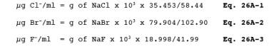
12.2
Calculate the exact Cl-, Br-, and F
concentration in the halide salt stock standard solutions using the following
equations.
12.3 Average Dry Gas
Meter Temperature and Average Orifice Pressure Drop. See data sheet (Figure 5-3 of Method 5).
12.4 Dry Gas Volume.
Calculate Vm(std) and adjust for leakage, if necessary, using the
equation in Section 12.3 of Method 5.
12.5 Volume of Water
Vapor and Moisture Content. Calculate the volume of water vapor Vw(std) and moisture content Bws from the data obtained in this method (Figure
5-3 of Method 5); use Equations 5-2 and 5-3 of
Method 5.
12.6 Isokinetic
Variation and Acceptable Results. Use Method 5,
Section 12.11.
12.7 Acetone Blank
Concentration, Acetone Wash Blank Residue Weight, Particulate Weight, and
Particulate Concentration. For particulate determination.
12.8 Total µg HCl,
HBr, or HF Per Sample.
![]()
12.9 Total µg Cl2 or Br2 Per Sample.
![]()
12.10 Concentration
of Hydrogen Halide or Halogen in Flue Gas.
![]()
12.11 Stack Gas
Velocity and Volumetric Flow Rate. Calculate the average stack gas velocity and
volumetric flow rate, if needed, using data obtained in this method and the
equations in Sections 12.3 and 12.4 of Method 2.
13.0 Method Performance.
13.1 Precision and Bias.
The method has a
possible measurable negative bias below 20 ppm HCl perhaps due to reaction with
small amounts of moisture in the probe and filter. Similar bias for the other
hydrogen halides is possible.
13.2 Sample Stability.
The collected Cl- samples can be stored for up to 4 weeks for analysis for HCl and Cl2.
13.3 Detection Limit.
A typical analytical
detection limit for HCl is 0.2 µg/ml. Detection limits for the other analyses
should be similar. Assuming 300 ml of liquid recovered for the acidified
impingers and a similar amounts recovered from the basic impingers, and 1 dscm
of stack gas sampled, the analytical detection limits in the stack gas would be
about 0.04 ppm for HCl and Cl2, respectively.
14.0 Pollution Prevention. [Reserved]
15.0 Waste Management. [Reserved]
16.0 References.
1. Steinsberger, S.
C. and J. H. Margeson. Laboratory and Field Evaluation of a Methodology for
Determination of Hydrogen Chloride Emissions from Municipal and Hazardous Waste
Incinerators. U.S. Environmental Protection Agency, Office of Research and
Development. Publication No. 600/3-89/064. April 1989. Available from National
Technical Information Service, Springfield, VA 22161 as PB89220586/AS.
2. State of
California Air Resources Board. Method 421 - Determination of Hydrochloric Acid
Emissions from Stationary Sources. March 18, 1987.
3. Cheney, J.L. and C.R.
Fortune. Improvements in the Methodology for Measuring Hydrochloric Acid in
Combustion Source Emissions. J. Environ. Sci. Health. A19(3): 337-350. 1984.
4. Stern, D.A., B.M.
Myatt, J.F. Lachowski, and K.T. McGregor. Speciation of Halogen and Hydrogen
Halide Compounds in Gaseous Emissions. In: Incineration and Treatment of
Hazardous Waste: Proceedings of the 9th Annual Research Symposium, Cincinnati,
Ohio, May 2-4, 1983. Publication No. 600/9-84-015. July 1984. Available from
National Technical Information Service, Springfield, VA 22161 as PB84-234525.
5. Holm, R.D. and
S.A. Barksdale. Analysis of Anions in Combustion Products. In: Ion
Chromatographic Analysis of Environmental Pollutants, E. Sawicki, J.D. Mulik,
and E. Wittgenstein (eds.). Ann Arbor, Michigan, Ann Arbor Science Publishers.
1978. pp. 99-110.
17.0 Tables, Diagrams, Flowcharts, and Validation Data.