METHOD
26 - DETERMINATION OF HYDROGEN HALIDE AND HALOGEN EMISSIONS FROM STATIONARY
SOURCES NON-ISOKINETIC METHOD
5.2.1 Sodium Hydroxide
(NaOH).
6.1.4 Drying Tube or
Impinger.
6.1.6 Filter Holder and
Support.
6.1.9 Purge Pump, Purge
Line, Drying Tube, Needle Valve, and Rate Meter.
6.1.10 Stopcock Grease,
Valve, Pump, Volume Meter, Barometer, and Vacuum Gauge.
6.1.11 Temperature
Measuring Devices.
6.3 Sample Preparation
and Analysis.
7.1.3 Acidic Absorbing
Solution, 0.1 N Sulfuric Acid (H2SO4).
7.1.5 Alkaline
Adsorbing Solution, 0.1 N Sodium Hydroxide (NaOH).
7.1.6 Sodium
Thiosulfate (Na2S2O3 .5 H2O)
7.2 Sample Preparation
and Analysis.
7.2.2 Absorbing
Solution Blanks.
7.2.3 Halide Salt Stock
Standard Solutions.
7.3 Quality Assurance
Audit Samples.
8.0 Sample Collection,
Preservation, Storage, and Transport.
8.1.1 Preparation of
Collection Train.
8.1.2 Adjust the probe
temperature and the temperature of the filter and the stopcock
8.3 Sample Preparation
for Analysis.
10.0 Calibration and
Standardization.
10.1 Volume Metering
System, Temperature Sensors, Rate Meter, and Barometer.
12.0 Data Analysis and
Calculations.
12.2 Calculate the
exact Cl-, Br-, and F- concentration
12.3 Sample Volume, Dry
Basis, Corrected to Standard Conditions.
12.4 Total µg HCl, HBr,
or HF Per Sample.
12.5 Total µg Cl2 or
Br2 Per Sample.
12.6 Concentration of
Hydrogen Halide or Halogen in Flue Gas.
14.0 Pollution
Prevention. [Reserved]
15.0 Waste Management.
[Reserved]
17.0 Tables, Diagrams,
Flowcharts, and Validation Data.
1.0 Scope and Application.
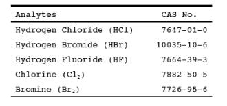
1.1 Analytes.
1.2 Applicability.
This method is
applicable for determining emissions of hydrogen halides (HX) [HCl, HBr, and
HF] and halogens (X2) [Cl2 and Br2] from stationary sources when specified by the applicable subpart.
Sources, such as those controlled by wet scrubbers, that emit acid particulate
matter must be sampled using Method 26A.
1.3 Data Quality Objectives.
Adherence to the
requirements of this method will enhance the quality of the data obtained from
air pollutant sampling methods.
2.0 Summary of Method.
2.1 An integrated
sample is extracted from the source and passed through a pre-purged heated
probe and filter into dilute sulfuric acid and dilute sodium hydroxide
solutions which collect the gaseous hydrogen halides and halogens, respectively.
The filter collects articulate matter including halide salts but is not
routinely recovered and analyzed. The hydrogen halides are solubilized in the
acidic solution and form chloride (Cl-), bromide
(Br-), and fluoride (F-)
ions. The halogens have a very low solubility in the acidic solution and pass
through to the alkaline solution where they are hydrolyzed to form a proton (H+), the halide ion, and the hypohalous acid (HClO or HBrO). Sodium
thiosulfate is added in excess to the alkaline solution to assure reaction with
the hypohalous acid to form a second halide ion such that 2 halide ions are
formed for each molecule of halogen gas. The halide ions in the separate
solutions are measured by ion chromatography (IC).
3.0 Definitions. [Reserved]
4.0 Interferences.
4.1 Volatile
materials, such as chlorine dioxide (ClO2) and
ammonium chloride (NH4Cl), which produce halide ions upon dissolution
during sampling are potential interferents. Interferents for the halide
measurements are the halogen gases which disproportionate to a hydrogen halide
and a hydrohalous acid upon dissolution in water. However, the use of acidic
rather than neutral or basic solutions for collection of the hydrogen halides
greatly reduces the dissolution of any halogens passing through this solution.
4.2 The simultaneous
presence of HBr and CL2
may cause a positive bias in the
HCL result with a corresponding negative bias in the Cl2 result as well as affecting the HBr/Br2 split.
4.3 High
concentrations of nitrogen oxides (NOx) may
produce sufficient nitrate (NO3-) to interfere with
measurements of very low Br- levels.
4.4 A glass wool plug
should not be used to remove particulate matter since a negative bias in the
data could result.
4.5 There is anecdotal
evidence that HF may be out-gassed from new Teflon components. If HF is a
target analyte, then preconditioning of new Teflon components, by heating
should be considered.
5.0 Safety
5.1 Disclaimer.
This method may
involve hazardous materials, operations, and equipment. This test method may
not address all of the safety problems associated with its use. It is the
responsibility of the user to establish appropriate safety and health practices
and determine the applicability of regulatory limitations before performing
this test method.
5.2 Corrosive Reagents.
The following
reagents are hazardous. Personal protective equipment and safe procedures are
useful in preventing chemical splashes. If contact occurs, immediately flush
with copious amounts of water for at least 15 minutes. Remove clothing under
shower and decontaminate. Treat residual chemical burns as thermal burns.
5.2.1 Sodium Hydroxide (NaOH).
Causes severe damage
to eyes and skin. Inhalation causes irritation to nose, throat, and lungs. Reacts
exothermically with limited amounts of water.
5.2.2 Sulfuric Acid (H2SO4).
Rapidly destructive
to body tissue. Will cause third degree burns. Eye damage may result in
blindness. Inhalation may be fatal from spasm of the larynx, usually within 30
minutes. May cause lung tissue damage with edema. 1 mg/m3 for 8 hours will cause lung damage or, in higher concentrations,
death. Provide ventilation to limit inhalation. Reacts violently with metals
and organics.
6.0 Equipment and Supplies.
NOTE: Mention of trade names or specific products does
not constitute endorsement by the Environmental Protection Agency.
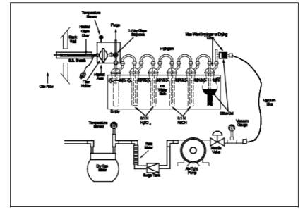
6.1 Sampling.
The sampling train is
shown in Figure 26-1, and component parts are discussed
below.
6.1.1 Probe.
Borosilicate glass,
approximately 3/8-in. (9-mm) I.D. with a heating system to prevent moisture
condensation. A Teflon-glass filter in a mat configuration should be installed
to remove particulate matter from the gas stream (see Section 6.1.6).
6.1.2 Three-way Stopcock.
A borosilicate-glass
three-way stopcock with a heating system to prevent moisture condensation. The
heated stopcock should connect to the outlet of the heated filter and the inlet
of the first impinger. The heating system should be capable of preventing
condensation up to the inlet of the first impinger. Silicone grease may be
used, if necessary, to prevent leakage.
6.1.3 Impingers.
Four 30-ml midget
impingers with leak-free glass connectors. Silicone grease may be used, if
necessary, to prevent leakage. For sampling at high moisture sources or for
sampling times greater than one hour, a midget impinger with a shortened stem
(such that the gas sample does not bubble through the collected condensate)
should be used in front of the first impinger.
6.1.4 Drying Tube or Impinger.
Tube or impinger, of
Mae West design, filled with 6- to 16-mesh indicating type silica gel, or
equivalent, to dry the gas sample and to protect the dry gas meter and pump. If
the silica gel has been used previously, dry at 175˚C (350˚F) for 2 hours. New
silica gel may be used as received. Alternatively, other types of desiccants
(equivalent or better) may be used.
6.1.5 Heating System.
Any heating system
capable of maintaining a temperature around the probe and filter holder greater
than 120˚C (248˚F) during sampling, or such other temperature as specified by
an applicable subpart of the standards or approved by the Administrator for a
particular application.
6.1.6 Filter Holder and Support.
The filter holder
shall be made of Teflon or quartz. The filter support shall be made of Teflon.
All Teflon filter holders and supports are available from Savillex Corp., 5325
Hwy 101, Minnetonka, MN 55345.
6.1.7 Sample Line.
Leak-free, with compatible
fittings to connect the last impinger to the needle valve.
6.1.8 Rate Meter.
Rotameter, or
equivalent, capable of measuring flow rate to within 2 percent of the selected
flow rate of 2 liters/min (0.07 ft3/min).
6.1.9 Purge Pump, Purge Line, Drying Tube, Needle Valve, and Rate Meter.
Pump capable of
purging the sampling probe at 2 liters/min, with drying tube, filled with
silica gel or equivalent, to protect pump, and a rate meter capable of
measuring 0 to 5 liters/min (0.2 ft3/min).
6.1.10 Stopcock Grease, Valve, Pump, Volume Meter, Barometer, and Vacuum Gauge.
Same as in Method 6, Sections 6.1.1.4, 6.1.1.7,
6.1.1.8, 6.1.1.10, 6.1.2, and 6.1.3.
6.1.11 Temperature Measuring Devices.
Temperature sensors
to monitor the temperature of the probe and to monitor the temperature of the
sampling system from the outlet of the probe to the inlet of the first
impinger.
6.1.12 Ice Water Bath.
To minimize loss of
absorbing solution.
6.2 Sample Recovery.
6.2.1 Wash Bottles.
Polyethylene or
glass, 500-ml or larger, two.
6.2.2 Storage
Bottles. 100- or 250-ml, high-density polyethylene bottles with Teflon screw
cap liners to store impinger samples.
6.3 Sample Preparation and Analysis.
The materials
required for volumetric dilution and chromatographic analysis of samples are
described below.
6.3.1 Volumetric
Flasks. Class A, 100-ml size.
6.3.2 Volumetric
Pipets. Class A, assortment. To dilute samples to the calibration range of the
ion chromatograph.
6.3.3 Ion Chromatograph
(IC). Suppressed or non-suppressed, with a conductivity detector and electronic
integrator operating in the peak area mode. Other detectors, strip chart
recorders, and peak height measurements may be used.
7.0 Reagents and Standards.
NOTE: Unless otherwise indicated, all reagents must
conform to the specifications established by the Committee on Analytical
Reagents of the American Chemical Society (ACS reagent grade). When such
specifications are not available, the best available grade shall be used.
7.1 Sampling.
7.1.1 Filter.
A 25-mm (1 in)(or
other size) Teflon glass mat, Pallflex TX40HI75 (Pallflex Inc., 125 Kennedy
Drive, Putnam, CT 06260). This filter is in a mat configuration to prevent fine
particulate matter from entering the sampling train. Its composition is 75%
Teflon/25% borosilicate glass. Other filters may be used, but they must be in a
mat (as opposed to a laminate) configuration and contain at least 75% Teflon.
For practical rather than scientific reasons, when the stack gas temperature
exceeds 210˚C (410˚F) and the HCl concentration is greater than 20 ppm, a
quartz-fiber filter may be used since Teflon becomes unstable above this
temperature.
7.1.2 Water.
Deionized, distilled
water that conforms to American Society of Testing and Materials (ASTM)
Specification D 1193-77 or 91, Type 3 (incorporated by reference - see §60.17).
7.1.3 Acidic Absorbing Solution, 0.1 N Sulfuric Acid (H2SO4).
To prepare 100 ml of
the absorbing solution for the front impinger pair, slowly add 0.28 ml of
concentrated H2SO4 to about
90 ml of water while stirring, and adjust the final volume to 100 ml using
additional water. Shake well to mix the solution.
7.1.4 Silica Gel.
Indicating type, 6 to
16 mesh. If previously used, dry at 180 ˚C (350 ˚F) for 2 hours. New silica gel
may be used as received. Alternatively, other types of desiccants may be used,
subject to the approval of the Administrator.
7.1.5 Alkaline Adsorbing Solution, 0.1 N Sodium Hydroxide (NaOH).
To prepare 100 ml of
the scrubber solution for the third and fourth impinger, dissolve 0.40 g of
solid NaOH in about 90 ml of water, and adjust the final solution volume to 100
ml using additional water. Shake well to mix the solution.
7.1.6 Sodium Thiosulfate (Na2S2O3 .5 H2O)
7.2 Sample Preparation and Analysis.
7.2.1 Water.
Same as in Section
7.1.2.
7.2.2 Absorbing Solution Blanks.
A separate blank
solution of each absorbing reagent should be prepared for analysis with the
field samples. Dilute 30 ml of each absorbing solution to approximately the
same final volume as the field samples using the blank sample of rinse water.
7.2.3 Halide Salt Stock Standard Solutions.
Prepare concentrated
stock solutions from reagent grade sodium chloride (NaCl), sodium bromide
(NaBr), and sodium fluoride (NaF). Each must be dried at 110˚C (230˚F) for two
or more hours and then cooled to room temperature in a desiccator immediately
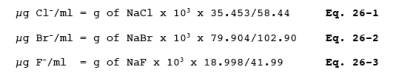
before weighing. Accurately weigh 1.6 to 1.7 g of the dried NaCl to within 0.1
mg, dissolve in water, and dilute to 1 liter. Calculate the exact Cl- concentration using Equation 26-1 in Section 12.2. In a similar
manner, accurately weigh and solubilize 1.2 to 1.3 g of dried NaBr and 2.2 to
2.3 g of NaF to make 1-liter solutions. Use Equations
26-2 and 26-3 in Section 12.2, to calculate the Br- and F- concentrations. Alternately, solutions
containing a nominal certified concentration of 1000 mg/l NaCl are commercially
available as convenient stock solutions from which standards can be made by
appropriate volumetric dilution. Refrigerate the stock standard solutions and
store no longer than one month.
7.2.4 Chromatographic Eluent.
Effective eluents for
nonsuppressed IC using a resin- or silica-based weak ion exchange column are a
4 mM potassium hydrogen phthalate solution, adjusted to pH 4.0 using a
saturated sodium borate solution, and a 4 mM 4-hydroxy benzoate solution,
adjusted to pH 8.6 using 1 N NaOH. An effective eluent for suppressed ion
chromatography is a solution containing 3 mM sodium bicarbonate and 2.4 mM
sodium carbonate. Other dilute solutions buffered to a similar pH and
containing no interfering ions may be used. When using suppressed ion
chromatography, if the "water dip" resulting from sample injection
interferes with the chloride peak, use a 2 mM NaOH/2.4 mM sodium bicarbonate
eluent.
7.3 Quality Assurance Audit Samples.
When making
compliance determinations, and upon availability, audit samples may be obtained
from the appropriate EPA regional Office or from the responsible enforcement
authority.
NOTE: The responsible enforcement authority should be
notified at least 30 days prior to the test date to allow sufficient time for
sample delivery.
8.0 Sample Collection, Preservation, Storage, and Transport.
NOTE: Because of the complexity of this method,
testers and analyst should be trained and experienced with the procedure to
ensure reliable results.
8.1 Sampling.
8.1.1 Preparation of Collection Train.
Prepare the sampling
train as follows: Pour 15 ml of the acidic absorbing solution into each one of
the first pair of impingers, and 15 ml of the alkaline absorbing solution into
each one of the second pair of impingers. Connect the impingers in series with
the knockout impinger first, if used, followed by the two impingers containing
the acidic absorbing solution and the two impingers containing the alkaline
absorbing solution. Place a fresh charge of silica gel, or equivalent, in the
drying tube or impinger at the end of the impinger train.
8.1.2 Adjust the probe temperature and the temperature of the filter and the stopcock
Adjust the probe
temperature and the temperature of the filter and the stopcock, i.e., the
heated area in Figure 26-1 to a temperature sufficient to prevent water
condensation. This temperature should be at least 20˚C (68˚F) above the source
temperature, and greater than 120˚C (248˚F). The temperature should be
monitored throughout a sampling run to ensure that the desired temperature is
maintained. It is important to maintain a temperature around the probe and
filter of greater than 120˚C (248˚F) since it is extremely difficult to purge
acid gases off these components. (These components are not quantitatively
recovered and hence any collection of acid gases on these components would
result in potential undereporting of these emissions. The applicable subparts
may specify alternative higher temperatures.)
8.1.3 Leak-Check Procedure.
8.1.3.1 Sampling Train.
A leak-check prior to
the sampling run is optional; however, a leak-check after the sampling run is
mandatory. The leak-check procedure is as follows: Temporarily attach a
suitable [e.g., 0-40 cc/min (0-2.4 in3/min)]
rotameter to the outlet of the dry gas meter and place a vacuum gauge at or
near the probe inlet. Plug the probe inlet, pull a vacuum of at least 250 mm Hg
(10 in. Hg), and note the flow rate as indicated by the rotameter. A leakage
rate not in excess of 2 percent of the average sampling rate is acceptable. (NOTE:
Carefully release the probe
inlet plug before turning off the pump.)
8.1.3.2 Pump.
It is suggested (not
mandatory) that the pump be leak-checked separately, either prior to or after
the sampling run. If done prior to the sampling run, the pump leak-check shall
precede the leak-check of the sampling train described immediately above; if
done after the sampling run, the pump leak-check shall follow the train
leak-check. To leak-check the pump, proceed as follows: Disconnect the drying
tube from the probe-impinger assembly. Place a vacuum gauge at the inlet to
either the drying tube or pump, pull a vacuum of 250 mm (10 in) Hg, plug or
pinch off the outlet of the flow meter, and then turn off the pump. The vacuum
should remain stable for at least 30 sec. Other leak-check procedures may be
used, subject to the approval of the Administrator, U.S. Environmental
Protection Agency.
8.1.4 Purge Procedure.
Immediately before
sampling, connect the purge line to the stopcock, and turn the stopcock to
permit the purge pump to purge the probe (see Figure 1A of Figure 26-1). Turn
on the purge pump, and adjust the purge rate to 2 liters/min (0.07 ft3/min). Purge for at least 5 minutes before sampling.
8.1.5 Sample Collection.
Turn on the sampling
pump, pull a slight vacuum of approximately 25 mm Hg (1 in Hg) on the impinger
train, and turn the stopcock to permit stack gas to be pulled through the
impinger train (see Figure 1C of Figure 26-1). Adjust the sampling rate to 2
liters/min, as indicated by the rate meter, and maintain this rate to within 10
percent during the entire sampling run. Take readings of the dry gas meter
volume and temperature, rate meter, and vacuum gauge at least once every five
minutes during the run. A sampling time of one hour is recommended. Shorter
sampling times may introduce a significant negative bias in the HCl
concentration. At the conclusion of the sampling run, remove the train from the
stack, cool, and perform a leak-check as described in Section 8.1.3.1.
8.2 Sample Recovery.
8.2.1 Disconnect the
impingers after sampling. Quantitatively transfer the contents of the acid
impingers and the knockout impinger, if used, to a leak-free storage bottle.
Add the water rinses of each of these impingers and connecting glassware to the
storage bottle.
8.2.2 Repeat this procedure
for the alkaline impingers and connecting glassware using a separate storage
bottle. Add 25 mg of sodium thiosulfate per the product of ppm of halogen
anticipated to be in the stack gas times the volume (dscm) of stack gas sampled
(0.7 mg per ppm-dscf).
[NOTE: This amount of sodium thiosulfate includes a
safety factor of approximately 5 to assure complete reaction with the
hypohalous acid to form a second Cl- ion in
the alkaline solution.]
8.2.3 Save portions
of the absorbing reagents (0.1 N H2SO4 and 0.1 N NaOH) equivalent to the amount used in the sampling train
(these are the absorbing solution blanks described in Section 7.2.2); dilute to
the approximate volume of the corresponding samples using rinse water directly
from the wash bottle being used. Add the same amount of sodium thiosulfate
solution to the 0.1 N NaOH absorbing solution blank. Also, save a portion of
the rinse water used to rinse the sampling train. Place each in a separate,
prelabeled storage bottle. The sample storage bottles should be sealed, shaken
to mix, and labeled. Mark the fluid level.
8.3 Sample Preparation for Analysis.
Note the liquid
levels in the storage bottles and confirm on the analysis sheet whether or not
leakage occurred during transport. If a noticeable leakage has occurred, either
void the sample or use methods, subject to the approval of the Administrator,
to correct the final results. Quantitatively transfer the sample solutions to
100-ml volumetric flasks, and dilute to 100 ml with water.
9.0 Quality Control.
10.0 Calibration and Standardization.
NOTE: Maintain a laboratory log of all calibrations.
10.1 Volume Metering System, Temperature Sensors, Rate Meter, and Barometer.
Same as in Method 6,
Sections 10.1, 10.2, 10.3, and 10.4.
10.2 Ion Chromatograph.
10.2.1 To prepare the
calibration standards, dilute given amounts (1.0 ml or greater) of the stock
standard solutions to convenient volumes, using 0.1 N H2SO4 or 0.1 N NaOH, as appropriate. Prepare at least
four calibration standards for each absorbing reagent containing the
appropriate stock solutions such that they are within the linear range of the
field samples.
10.2.2 Using one of
the standards in each series, ensure adequate baseline separation for the peaks
of interest.
10.2.3 Inject the appropriate
series of calibration standards, starting with the lowest concentration
standard first both before and after injection of the quality control check
sample, reagent blanks, and field samples. This allows compensation for any
instrument drift occurring during sample analysis. The values from duplicate
injections of these calibration samples should agree within 5 percent of their
mean for the analysis to be valid.
10.2.4 Determine the
peak areas, or heights, for the standards and plot individual values versus
halide ion concentrations in µg/ml.
10.2.5 Draw a smooth
curve through the points. Use linear regression to calculate a formula
describing the resulting linear curve.
11.0 Analytical Procedures.
11.1 Sample Analysis.
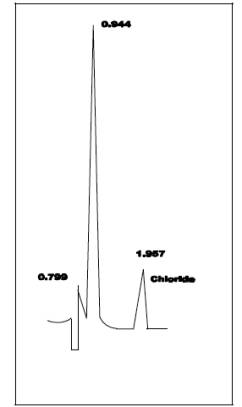
11.1.1 The IC conditions
will depend upon analytical column type and whether suppressed or
non-suppressed IC is used. An example chromatogram from a non-suppressed system
using a 150-mm Hamilton PRP-X100 anion column, a 2 ml/min flow rate of a 4 mM
4-hydroxy benzoate solution adjusted to a pH of 8.6 using 1 N NaOH, a 50 µl
sample loop, and a conductivity detector set on 1.0 µS full scale is shown in Figure 26-2.
11.1.2 Before sample
analysis, establish a stable baseline. Next, inject a sample of water, and
determine if any Cl-, Br-, or F- appears in the chromatogram. If any of these ions are present,
repeat the load/injection procedure until they are no longer present. Analysis
of the acid and alkaline absorbing solution samples requires separate standard
calibration curves; prepare each according to Section 10.2. Ensure adequate
baseline separation of the analyses.
11.1.3 Between
injections of the appropriate series of calibration standards, inject in
duplicate the reagent blanks, quality control sample, and the field samples.
Measure the areas or heights of the Cl-, Br-, and F-
peaks. Use the mean response of the
duplicate injections to determine the concentrations of the field samples and
reagent blanks using the linear calibration curve. The values from duplicate
injections should agree within 5 percent of their mean for the analysis to be
valid. If the values of duplicate injections are not within 5 percent of the
mean, the duplicate injections shall be repeated and all four values used to
determine the average response. Dilute any sample and the blank with equal
volumes of water if the concentration exceeds that of the highest standard.
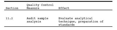
11.2 Audit Sample Analysis.
11.2.1 When the
method is used to analyze samples to demonstrate compliance with a source
emission regulation, a set of two EPA audit samples must be analyzed, subject
to availability.
11.2.2 Concurrently
analyze the audit samples and the compliance samples in the same manner to
evaluate the technique of the analyst and the standards preparation.
11.2.3 The same
analyst, analytical reagents, and analytical system shall be used for the
compliance samples and the EPA audit samples. If this condition is met,
duplicate auditing of subsequent compliance analyses for the same enforcement
agency within a 30-day period is waived. An audit sample set may not be used to
validate different sets of compliance samples under the jurisdiction of
separate enforcement agencies, unless prior arrangements have been made with
both enforcement agencies.
11.3 Audit Sample Results.
11.3.1 Calculate the
concentrations in mg/L of audit sample and submit results following the
instructions provided with the audit samples.
11.3.2 Report the
results of the audit samples and the compliance determination samples along
with their identification numbers, and the analyst's name to the responsible
enforcement authority. Include this information with reports of any subsequent
compliance analyses for the same enforcement authority during the 30-day
period.
11.3.3 The
concentrations of the audit samples obtained by the analyst shall agree within
10 percent of the actual concentrations. If the 10 percent specification is not
met, reanalyze the compliance and audit samples, and include initial and
reanalysis values in the test report.
11.3.4 Failure to
meet the 10 percent specification may require retests until the audit problems
are resolved. However, if the audit results do not affect the compliance or noncompliance
status of the affected facility, the Administrator may waive the reanalysis
requirement, further audits, or retests and accept the results of the
compliance test. While steps are being taken to resolve audit analysis
problems, the Administrator may also choose to use the data to determine the
compliance or noncompliance status of the affected facility.
12.0 Data Analysis and Calculations.
NOTE: Retain at least one extra decimal figure beyond
those contained in the available data in intermediate calculations, and round
off only the final answer appropriately.
12.1 Nomenclature.
BX- = Mass concentration of applicable absorbing
solution blank, µg halide ion (Cl-, Br-, F-) /ml, not to exceed 1 µg/ml which is 10 times the
published analytical detection limit of 0.1 µg/ml.
C = Concentration of
hydrogen halide (HX) or halogen (X2), dry
basis, mg/dscm.
K = 10-3 mg/µg.
KHCl = 1.028 (µg HCl/µg-mole)/(µg Cl-/µg-mole).
KHBr = 1.013 (µg HBr/µg-mole)/(µg Br-/µg-mole).
KHF = 1.053 (µg HF/µg-mole)/(µg F-/µg-mole).
mHX = Mass of HCl, HBr, or HF in sample, µg.
mX2 = Mass of Cl2 or Br2 in sample, µg.
SX- = Analysis of sample, µg halide ion (Cl-, Br-, F-)/ml.
Vm(std)= Dry gas volume measured by the dry gas meter,
corrected to standard conditions, dscm.
Vs = Volume of filtered and diluted sample, ml.
12.2 Calculate the exact Cl-, Br-, and F- concentration
Calculate the exact
Cl-, Br-, and F-
concentration in the halide salt stock standard solutions using the following
equations.
12.3 Sample Volume, Dry Basis, Corrected to Standard Conditions.
Calculate the sample
volume using Eq. 6-1 of Method 6.
12.4 Total µg HCl, HBr, or HF Per Sample.
![]()
12.5 Total µg Cl2 or Br2 Per Sample.
![]()
12.6 Concentration of Hydrogen Halide or Halogen in Flue Gas.
![]()
13.0 Method Performance.
13.1 Precision and Bias.
The within-laboratory
relative standard deviations are 6.2 and 3.2 percent at Hcl concentrations of
3.9 and 15.3 ppm, respectively. The method does not exhibit a bias to Cl2 when sampling at concentrations less than 50 ppm.
13.2 Sample Stability.
The collected Cl- samples can be stored for up to 4 weeks.
13.3 Detection Limit.
A typical IC
instrumental detection limit for Cl- is 0.2
µg/ml. Detection limits for the other analyses should be similar. Assuming 50
ml liquid recovered from both the acidified impingers, and the basic impingers,
and 0.06 dscm of stack gas sampled, then the analytical detection limit in the
stack gas would be about 0.1 ppm for HCl and Cl2,
respectively.
14.0 Pollution Prevention. [Reserved]
15.0 Waste Management. [Reserved]
16.0 References.
1. Steinsberger, S.
C. and J. H. Margeson, "Laboratory and Field Evaluation of a Methodology
for Determination of Hydrogen Chloride Emissions from Municipal and Hazardous
Waste Incinerators," U.S. Environmental Protection Agency, Office of
Research and Development, Report No. 600/3-89/064, April 1989. Available from
the National Technical Information Service, Springfield, VA 22161 as PB89220586/AS.
2. State of
California, Air Resources Board, Method 421, "Determination of
Hydrochloric Acid Emissions from Stationary Sources," March 18, 1987.
3. Cheney, J.L. and
C.R. Fortune. Improvements in the Methodology for Measuring Hydrochloric Acid
in Combustion Source Emissions. J. Environ. Sci. Health. A19(3): 337-350. 1984.
4. Stern, D. A., B.
M. Myatt, J. F. Lachowski, and K. T. McGregor. Speciation of Halogen and
Hydrogen Halide Compounds in Gaseous Emissions. In: Incineration and Treatment
of Hazardous Waste: Proceedings of the 9th Annual Research Symposium,
Cincinnati, Ohio, May 2-4, 1983. Publication No. 600/9-84-015. July 1984.
Available from National Technical Information Service, Springfield, VA 22161 as
PB84-234525.
5. Holm, R. D. and S.
A. Barksdale. Analysis of Anions in Combustion Products. In: Ion
Chromatographic Analysis of Environmental Pollutants. E. Sawicki, J. D. Mulik,
and E. Wittgenstein (eds.). Ann Arbor, Michigan, Ann Arbor Science Publishers.
1978. pp. 99-110.
17.0 Tables, Diagrams, Flowcharts, and Validation Data.
Figure
26-2. Example Chromatogram.