METHOD 25A -
DETERMINATION OF TOTAL GASEOUS ORGANIC CONCENTRATION USING A FLAME IONIZATION
ANALYZER
6.1.1 Organic
Concentration Analyzer.
6.1.4 Calibration Valve
Assembly.
7.1.3 Low-level
Calibration Gas.
7.1.4 Mid-level
Calibration Gas.
7.1.5 High-level
Calibration Gas.
8.0 Sample Collection,
Preservation, Storage, and Transport.
8.1 Selection of
Sampling Site.
8.3 Measurement System
Preparation.
8.6 Emission
Measurement Test Procedure.
10.0 Calibration and
Standardization.
12.0 Calculations and
Data Analysis.
14.0 Pollution
Prevention. [Reserved]
15.0 Waste Management.
[Reserved]
17.0 Tables, Diagrams,
Flowcharts, and Validation Data.
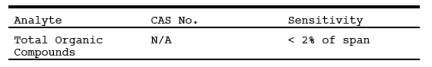
1.0 Scope and Application.
1.1 Analytes.
1.2 Applicability.
This method is applicable for the determination of total gaseous organic
concentration of vapors consisting primarily of alkanes, alkenes, and/or arenes
(aromatic hydrocarbons). The concentration is expressed in terms of propane (or
other appropriate organic calibration gas) or in terms of carbon.
1.3 Data Quality
Objectives. Adherence to the requirements of this method will enhance the
quality of the data obtained from air pollutant sampling methods.
2.0 Summary of Method.
2.1 A gas sample is extracted
from the source through a heated sample line and glass fiber filter to a flame
ionization analyzer (FIA). Results are reported as volume concentration
equivalents of the calibration gas or as carbon equivalents.
3.0 Definitions.
3.1 Calibration drift
Means the difference
in the measurement system response to a mid-level calibration gas before and
after a stated period of operation during which no unscheduled maintenance,
repair, or adjustment took place.
3.2 Calibration error
Means the difference
between the gas concentration indicated by the measurement system and the know
concentration of the calibration gas.
3.3 Calibration gas
Means a known
concentration of a gas in an appropriate diluent gas.
3.4 Measurement system
Means the total
equipment required for the determination of the gas concentration. The system
consists of the following major subsystems:
3.4.1 Sample interface
Means that portion of
a system used for one or more of the following: sample acquisition, sample
transportation, sample conditioning, or protection of the analyzer(s) from the
effects of the stack effluent.
3.4.2 Organic analyzer
Means that portion of
the measurement system that senses the gas to be measured and generates an
output proportional to its concentration.
3.5 Response time
Means the time
interval from a step change in pollutant concentration at the inlet to the
emission measurement system to the time at which 95 percent of the
corresponding final value is reached as displayed on the recorder.
3.6 Span Value
Means the upper limit
of a gas concentration measurement range that is specified for affected source
categories in the applicable part of the regulations. The span value is
established in the applicable regulation and is usually 1.5 to 2.5 times the
applicable emission limit. If no span value is provided, use a span value
equivalent to 1.5 to 2.5 times the expected concentration. For convenience, the
span value should correspond to 100 percent of the recorder scale.
3.7 Zero drift
Means the difference
in the measurement system response to a zero level calibration gas before or
after a stated period of operation during which no unscheduled maintenance,
repair, or adjustment took place.
4.0 Interferences. [Reserved]
5.0 Safety.
5.1 Disclaimer. This
method may involve hazardous materials, operations, and equipment. This test
method may not address all of the safety problems associated with its use. It
is the responsibility of the user of this test method to establish appropriate
safety and health practices and determine the applicability of regulatory
limitations prior to performing this test method. The analyzer users manual
should be consulted for specific precautions to be taken with regard to the
analytical procedure.
5.2 Explosive Atmosphere.
This method is often applied in highly explosive areas. Caution and care should
be exercised in choice of equipment and installation.
6.0 Equipment and Supplies
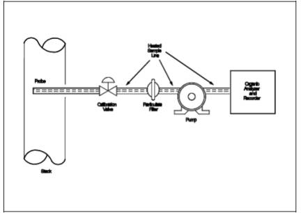
6.1 Measurement System.
Any measurement
system for total organic concentration that meets the specifications of this
method. A schematic of an acceptable measurement system is shown in Figure 25A-1. All sampling components leading to the
analyzer shall be heated > 110ºC (220ºF) throughout the sampling period,
unless safety reasons are cited (Section 5.2). The essential components of the
measurement system are described below:
6.1.1 Organic Concentration Analyzer.
A flame ionization
analyzer (FIA) capable of meeting or exceeding the specifications of this
method. The flame ionization detector block shall be heated >120EºC (250ºF).
6.1.2 Sample Probe.
Stainless steel, or
equivalent, three-hole rake type. Sample holes shall be 4 mm (0.16-in.) in
diameter or smaller and located at 16.7, 50, and 83.3 percent of the equivalent
stack diameter. Alternatively, a single opening probe may be used so that a gas
sample is collected from the centrally located 10 percent area of the stack
cross-section.
6.1.3 Heated Sample Line.
Stainless steel or
Teflon® tubing to transport the sample gas to the analyzer. The sample line
should be heated (>110 ºC) to prevent any condensation.
6.1.4 Calibration Valve Assembly.
A three-way valve
assembly to direct the zero and calibration gases to the analyzers is
recommended. Other methods, such as quick-connect lines, to route calibration
gas to the analyzers are applicable.
6.1.5 Particulate Filter.
An in-stack or an
out-of-stack glass fiber filter is recommended if exhaust gas particulate
loading is significant. An out-of-stack filter should be heated to prevent any
condensation.
6.1.6 Recorder.
A strip-chart
recorder, analog computer, or digital recorder for recording measurement data.
The minimum data-recording requirement is one measurement value per minute.
7.0 Reagents and Standards.
7.1 Calibration Gases.
The calibration gases
for the gas analyzer shall be propane in air or propane in nitrogen.
Alternatively, organic compounds other than propane can be used; the
appropriate corrections for response factor must be made. Calibration gases
shall be prepared in accordance with the procedure listed in Citation 2 of Section 16. Additionally, the manufacturer of the
cylinder should provide a recommended shelf life for each calibration gas
cylinder over which the concentration does not change more than ± 2 percent
from the certified value. For calibration gas values not generally available (i.e., organics between 1 and 10 percent by volume),
alternative methods for preparing calibration gas mixtures, such as dilution
systems (Test Method 205, 40 CFR Part 51, Appendix M), may be used with prior
approval of the Administrator.
7.1.1 Fuel.
A 40 percent H2/60 percent N2
or He gas mixture is recommended to
avoid an oxygen synergism effect that reportedly occurs when oxygen
concentration varies significantly from a mean value.
7.1.2 Zero Gas.
High purity air with
less than 0.1 part per million by volume (ppmv) of organic material (propane or
carbon equivalent) or less than 0.1 percent of the span value, whichever is
greater.
7.1.3 Low-level Calibration Gas.
An organic
calibration gas with a concentration equivalent to 25 to 35 percent of the
applicable span value.
7.1.4 Mid-level Calibration Gas.
An organic
calibration gas with a concentration equivalent to 45 to 55 percent of the
applicable span value.
7.1.5 High-level Calibration Gas.
An organic
calibration gas with a concentration equivalent to 80 to 90 percent of the
applicable span value.
8.0 Sample Collection, Preservation, Storage, and
Transport.
8.1 Selection of Sampling Site.
The location of the
sampling site is generally specified by the applicable regulation or purpose of
the test (i.e., exhaust stack, inlet line, etc.). The sample port shall be
located to meet the testing requirements of Method 1.
8.2 Location of Sample Probe.
Install the sample
probe so that the probe is centrally located in the stack, pipe, or duct and is
sealed tightly at the stack port connection.
8.3 Measurement System Preparation.
Prior to the emission
test, assemble the measurement system by following the manufacturer's written
instructions for preparing sample interface and the organic analyzer. Make the
system operable (Section 10.1).
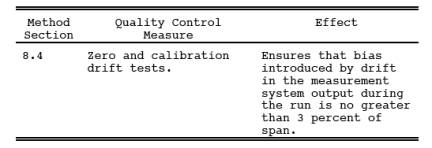
8.4 Calibration Error Test.
Immediately prior to
the test series (within 2 hours of the start of the test), introduce zero gas
and high-level calibration gas at the calibration valve assembly. Adjust the
analyzer output to the appropriate levels, if necessary. Calculate the
predicted response for the low-level and mid-level gases based on a linear
response line between the zero and high-level response. Then introduce
low-level and mid-level calibration gases successively to the measurement
system. Record the analyzer responses for low-level and mid-level calibration
gases and determine the differences between the measurement system responses
and the predicted responses. These differences must be less than 5 percent of
the respective calibration gas value. If not, the measurement system is not
acceptable and must be replaced or repaired prior to testing. No adjustments to
the measurement system shall be conducted after the calibration and before the
drift check (Section 8.6.2). If adjustments are necessary before the completion
of the test series, perform the drift checks prior to the required adjustments
and repeat the calibration following the adjustments. If multiple electronic
ranges are to be used, each additional range must be checked with a mid-level
calibration gas to verify the multiplication factor.
8.5 Response Time Test.
Introduce zero gas
into the measurement system at the calibration valve assembly. When the system
output has stabilized, switch quickly to the high-level calibration gas. Record
the time from the concentration change to the measurement system response
equivalent to 95 percent of the step change. Repeat the test three times and
average the results.
8.6 Emission Measurement Test Procedure.
8.6.1 Organic Measurement.
Begin sampling at the
start of the test period, recording time and any required process information
as appropriate. In particulate, note on the recording chart, periods of process
interruption or cyclic operation.
8.6.2 Drift Determination.
Immediately following
the completion of the test period and hourly during the test period,
reintroduce the zero and mid-level calibration gases, one at a time, to the
measurement system at the calibration valve assembly. (Make no adjustments to
the measurement system until both the zero and calibration drift checks are
made.) Record the analyzer response. If the drift values exceed the specified
limits, invalidate the test results preceding the check and repeat the test following
corrections to the measurement system. Alternatively, recalibrate the test
measurement system as in Section 8.4 and report the results using both sets of
calibration data (i.e., data determined prior to the test period and data
determined following the test period).
NOTE: Note on the recording chart periods of process
interruption or cyclic operation.
9.0 Quality Control
10.0 Calibration and Standardization.
10.1 FIA equipment can
be calibrated for almost any range of total organic concentrations. For high
concentrations of organics (> 1.0 percent by volume as propane),
modifications to most commonly available analyzers are necessary. One accepted
method of equipment modification is to decrease the size of the sample to the
analyzer through the use of a smaller diameter sample capillary. Direct and
continuous measurement of organic concentration is a necessary consideration
when determining any modification design.
11.0 Analytical Procedure.
The sample collection
and analysis are concurrent for this method (see Section
8.0).
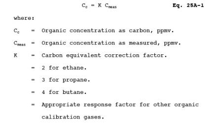
12.0 Calculations and Data Analysis.
12.1 Determine the
average organic concentration in terms of ppmv as propane or other calibration
gas. The average shall be determined by integration of the output recording
over the period specified in the applicable regulation. If results are required
in terms of ppmv as carbon, adjust measured concentrations using Equation
25A-1.
13.0 Method Performance.
13.1 Measurement
System Performance Specifications.
13.1.1 Zero Drift.
Less than ±3 percent of the span value.
13.1.2 Calibration
Drift. Less than ±3 percent of span value.
13.1.3 Calibration
Error. Less than ±5 percent of the calibration gas value.
14.0 Pollution Prevention. [Reserved]
15.0 Waste Management. [Reserved]
16.0 References.
1. Measurement of
Volatile Organic Compounds-Guideline Series. U.S. Environmental Protection Agency.
Research Triangle Park, NC. Publication No. EPA-450/2-78-041. June 1978. p.
46-54.
2. EPA Traceability
Protocol for Assay and Certification of Gaseous Calibration Standards. U.S.
Environmental Protection Agency, Quality Assurance and Technical Support
Division. Research Triangle Park, N.C. September 1993.
3. Gasoline Vapor
Emission Laboratory Evaluation-Part 2. U.S. Environmental Protection Agency,
Office of Air Quality Planning and Standards. Research Triangle Park, NC. EMB
Report No. 75-GAS-6. August 1975.
17.0 Tables, Diagrams, Flowcharts, and Validation Data.
Figure
25A-1. Organic Concentration Measurement System.