METHOD 12 - DETERMINATION OF INORGANIC LEAD EMISSIONS FROM STATIONARY SOURCES
NOTE: This method does not include all of the
specifications (e.g.,
equipment and supplies) and procedures (e.g., sampling and analytical) essential to its
performance. Some material is incorporated by reference from other methods in
this part. Therefore, to obtain reliable results, persons using this method
should have a thorough knowledge of at least the following additional test
methods: Method 1, Method 2,
Method 3, and Method 5.
8.0 Sample Collection,
Preservation, Storage, and Transport.
10.0 Calibration and
Standardizations.
11.3 Spectrophotometer
Preparation.
11.5 Check for Matrix
Effects.
12.0 Data Analysis and
Calculations.
14.0 Pollution
Prevention. [Reserved]
15.0 Waste Management.
[Reserved]
16.1 Simultaneous
Determination of Particulate and Lead Emissions.
18.0 Tables, Diagrams,
Flowcharts, and Validation Data.
1.0 Scope and Application.
1.1 Analytes.
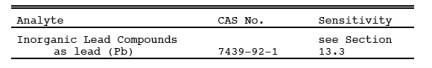
1.2 Applicability.
This method is
applicable for the determination of inorganic lead emissions from stationary
sources, only as specified in an applicable subpart of the regulations.
1.3 Data Quality Objectives.
Adherence to the
requirements of this method will enhance the quality of the data obtained from
air pollutant sampling methods.
2.0 Summary of Method.
2.1 Particulate and
gaseous Pb emissions are withdrawn isokinetically from the source and are
collected on a filter and in dilute nitric acid. The collected samples are
digested in acid solution and are analyzed by atomic absorption
spectrophotometry using an air/acetylene flame.
3.0 Definitions. [Reserved]
4.0 Interferences.
4.1 Copper.
High concentrations
of copper may interfere with the analysis of Pb at 217.0 nm. This interference
can be avoided by analyzing the samples at 283.3 nm.
4.2 Matrix Effects.
Analysis for Pb by
flame atomic absorption spectrophotometry is sensitive to the chemical
composition and to the physical properties (e.g., viscosity, pH) of the sample. The analytical
procedure requires the use of the Method of Standard Additions to check for
these matrix effects, and requires sample analysis using the Method of Standard
Additions if significant matrix effects are found to be present.
5.0 Safety.
5.1 Disclaimer.
This method may
involve hazardous materials, operations, and equipment. This test method may
not address all of the safety problems associated with its use. It is the
responsibility of the user of this test method to establish appropriate safety
and health practices and to determine the applicability of regulatory
limitations prior to performing this test method.
5.2 Corrosive Reagents.
The following
reagents are hazardous. Personal protective equipment and safe procedures are
useful in preventing chemical splashes. If contact occurs, immediately flush
with copious amounts of water at least 15 minutes. Remove clothing under shower
and decontaminate. Treat residual chemical burn as thermal burn.
5.2.1 Hydrogen
Peroxide (H2O2). Irritating to eyes,
skin, nose, and lungs.
5.2.2 Nitric Acid
(HNO3). Highly corrosive to eyes, skin, nose, and lungs.
Vapors cause bronchitis, pneumonia, or edema of lungs. Reaction to inhalation
may be delayed as long as 30 hours and still be fatal. Provide ventilation to
limit exposure. Strong oxidizer. Hazardous reaction may occur with organic
materials such as solvents.
6.0 Equipment and Supplies.
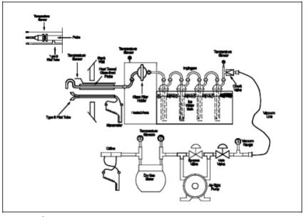
6.1 Sample Collection.
A schematic of the
sampling train used in performing this method is shown in Figure
12-1 in Section 18.0; it is similar to the Method 5 train. The following
items are needed for sample collection:
6.1.1 Probe Nozzle,
Probe Liner, Pitot Tube, Differential Pressure Gauge, Filter Holder, Filter
Heating System, Temperature Sensor, Metering System, Barometer, and Gas Density
Determination Equipment. Same as Method 5,
Sections 6.1.1.1 through 6.1.1.7, 6.1.1.9, 6.1.2, and 6.1.3, respectively.
6.1.2 Impingers. Four
impingers connected in series with leak-free ground glass fittings or any
similar leak-free noncontaminating fittings are needed. For the first, third,
and fourth impingers, use the Greenburg-Smith design, modified by replacing the
tip with a 1.3 cm (1/2 in.) ID glass tube extending to about 1.3 cm (1/2 in.)
from the bottom of the flask. For the second impinger, use the Greenburg-Smith
design with the standard tip.
6.1.3 Temperature
Sensor. Place a temperature sensor, capable of measuring temperature to within
1ºC (2ºF) at the outlet of the fourth impinger for monitoring purposes.
6.2 Sample Recovery.
The following items
are needed for sample recovery:
6.2.1 Probe-Liner and
Probe-Nozzle Brushes, Petri Dishes, Graduated Cylinder and/or Balance, Plastic
Storage Containers, and Funnel and Rubber Policeman. Same as Method 5, Sections 6.2.1 and 6.2.4 through
6.2.7, respectively.
6.2.2 Wash Bottles.
Glass (2).
6.2.3 Sample Storage
Containers. Chemically resistant, borosilicate glass bottles, for 0.1 N nitric
acid (HNO3) impinger and probe solutions and washes,
1000-ml. Use screw-cap liners that are either rubber-backed Teflon or leak-free
and resistant to chemical attack by 0.1 N HNO3.
(Narrow mouth glass bottles have been found to be less prone to leakage.)
6.2.4 Funnel. Glass,
to aid in sample recovery.
6.3 Sample Analysis.
The following items
are needed for sample analysis:
6.3.1 Atomic
Absorption Spectrophotometer. With lead hollow cathode lamp and burner for
air/acetylene flame.
6.3.2 Hot Plate.
6.3.3 Erlenmeyer
Flasks. 125-ml, 24/40 standard taper.
6.3.4 Membrane Filters.
Millipore SCWPO 4700, or equivalent.
6.3.5 Filtration
Apparatus. Millipore vacuum filtration unit, or equivalent, for use with the
above membrane filter.
6.3.6 Volumetric
Flasks. 100-ml, 250-ml, and 1000-ml.
7.0 Reagents and Standards.
NOTE: Unless otherwise indicated, it is intended that
all reagents conform to the specifications established by the Committee on
Analytical Reagents of the American Chemical Society, where such specifications
are available; otherwise, use the best available grade.
7.1 Sample Collection.
The following
reagents are needed for sample collection:
7.1.1 Filter. Gelman
Spectro Grade, Reeve Angel 934 AH, MSA 1106 BH, all with lot assay for Pb, or
other high purity glass fiber filters, without organic binder, exhibiting at
least 99.95 percent efficiency (<0.05 percent penetration) on 0.3 micron
dioctyl phthalate smoke particles. Conduct the filter efficiency test using
ASTM D 2986-71, 78, or 95a (incorporated by reference - see § 60.17) or use
test data from the supplier's quality control program.
7.1.2 Silica Gel,
Crushed Ice, and Stopcock Grease. Same as Method
5, Sections 7.1.2, 7.1.4, and 7.1.5, respectively.
7.1.3 Water.
Deionized distilled, to conform to ASTM D 1193-77 or 91, Type 3 (incorporated
by reference--see § 60.17). If high concentrations of organic matter are not
expected to be present, the potassium permanganate test for oxidizable organic
matter may be omitted.
7.1.4 Nitric Acid,
0.1 N. Dilute 6.5 ml of concentrated HNO3 to 1
liter with water. (It may be desirable to run blanks before field use to
eliminate a high blank on test samples.)
7.2 Sample Recovery.
0.1 N HNO3 (Same as in Section 7.1.4 above).
7.3 Sample Analysis.
The following
reagents and standards are needed for sample analysis:
7.3.1 Water. Same as
in Section 7.1.3.
7.3.2 Nitric Acid,
Concentrated.
7.3.3 Nitric Acid, 50
Percent (v/v). Dilute 500 ml of concentrated HNO3 to
1 liter with water.
7.3.4 Stock Lead Standard
Solution, 1000 µg Pb/ml. Dissolve 0.1598 g of lead nitrate [Pb(NO3)2] in about 60 ml water, add 2 ml concentrated
HNO3, and dilute to 100 ml with water.
7.3.5 Working Lead
Standards. Pipet 0.0, 1.0, 2.0, 3.0, 4.0, and 5.0 ml of the stock lead standard
solution (Section 7.3.4) into 250-ml volumetric flasks. Add 5 ml of
concentrated HNO3 to each flask, and dilute to volume with water.
These working standards contain 0.0, 4.0, 8.0, 12.0, 16.0, and 20.0 µg Pb/ml,
respectively. Prepare, as needed, additional standards at other concentrations
in a similar manner.
7.3.6 Air. Suitable
quality for atomic absorption spectrophotometry.
7.3.7 Acetylene.
Suitable quality for atomic absorption spectrophotometry.
7.3.8 Hydrogen
Peroxide, 3 Percent (v/v). Dilute 10 ml of 30 percent H2O2 to 100 ml with water.
8.0 Sample Collection, Preservation, Storage, and
Transport.
8.1 Pretest
Preparation. Follow the same general procedure given in Method 5, Section 8.1, except that the filter
need not be weighed.
8.2 Preliminary
Determinations. Follow the same general procedure given in Method 5, Section 8.2.
8.3 Preparation of
Sampling Train. Follow the same general procedure given in Method 5, Section 8.3, except place 100 ml of
0.1 N HNO3 (instead of water) in each of the first two
impingers. As in Method 5, leave the third impinger empty and transfer
approximately 200 to 300 g of pre-weighed silica gel from its container to the
fourth impinger. Set up the train as shown in Figure 12-1.
8.4 Leak-Check
Procedures. Same as Method 5, Section 8.4.
8.5 Sampling Train
Operation. Same as Method 5, Section 8.5.
8.6 Calculation of
Percent Isokinetic. Same as Method 5, Section 8.6.
8.7 Sample Recovery.
Same as Method 5, Sections 8.7.1 through
8.7.6.1, with the addition of the following:
8.7.1 Container No. 2
(Probe).
8.7.1.1 Taking care
that dust on the outside of the probe or other exterior surfaces does not get
into the sample, quantitatively recover sample matter and any condensate from
the probe nozzle, probe fitting, probe liner, and front half of the filter
holder by washing these components with 0.1 N HNO3 and
placing the wash into a glass sample storage container. Measure and record (to
the nearest 2 ml) the total amount of 0.1 N HNO3 used
for these rinses. Perform the 0.1 N HNO3 rinses as
follows:
8.7.1.2 Carefully
remove the probe nozzle, and rinse the inside surfaces with 0.1 N HNO3 from a wash bottle while brushing with a stainless steel,
Nylon-bristle brush. Brush until the 0.1 N HNO3 rinse
shows no visible particles, then make a final rinse of the inside surface with
0.1 N HNO3.
8.7.1.3 Brush and
rinse with 0.1 N HNO3
the inside parts of the Swagelok
fitting in a similar way until no visible particles remain.
8.7.1.4 Rinse the
probe liner with 0.1 N HNO3. While rotating the probe so that all inside
surfaces will be rinsed with 0.1 N HNO3, tilt the
probe, and squirt 0.1 N HNO3 into its upper end.
Let the 0.1 N HNO3 drain from the lower end into the sample
container. A glass funnel may be used to aid in transferring liquid washes to
the container. Follow the rinse with a probe brush. Hold the probe in an
inclined position, squirt 0.1 N HNO3 into the
upper end of the probe as the probe brush is being pushed with a twisting
action through the probe; hold the sample container underneath the lower end of
the probe, and catch any 0.1 N HNO3 and
sample matter that is brushed from the probe. Run the brush through the probe
three times or more until no visible sample matter is carried out with the 0.1
N HNO3 and none remains on the probe liner on visual
inspection. With stainless steel or other metal probes, run the brush through
in the above-prescribed manner at least six times, since metal probes have
small crevices in which sample matter can be entrapped. Rinse the brush with
0.1 N HNO3, and quantitatively collect these washings in
the sample container. After the brushing, make a final rinse of the probe as
described above.
8.7.1.5 It is
recommended that two people clean the probe to minimize loss of sample. Between
sampling runs, keep brushes clean and protected from contamination.
8.7.1.6 After
ensuring that all joints are wiped clean of silicone grease, brush and rinse
with 0.1 N HNO3 the inside of the from half of the filter
holder. Brush and rinse each surface three times or more, if needed, to remove
visible sample matter. Make a final rinse of the brush and filter holder. After
all 0.1 N HNO3 washings and sample matter are collected in the
sample container, tighten the lid on the sample container so that the fluid
will not leak out when it is shipped to the laboratory. Mark the height of the
fluid level to determine whether leakage occurs during transport. Label the
container to identify its contents clearly.
8.7.2 Container No. 3
(Silica Gel). Note the color of the indicating silica gel to determine if it
has been completely spent, and make a notation of its condition. Transfer the
silica gel from the fourth impinger to the original container, and seal. A
funnel may be used to pour the silica gel from the impinger and a rubber
policeman may be used to remove the silica gel from the impinger. It is not
necessary to remove the small amount of particles that may adhere to the walls
and are difficult to remove. Since the gain in weight is to be used for
moisture calculations, do not use any water or other liquids to transfer the
silica gel. If a balance is available in the field, follow the procedure for
Container No. 3 in Section 11.4.2.
8.7.3 Container No. 4
(Impingers). Due to the large quantity of liquid involved, the impinger
solutions may be placed in several containers. Clean each of the first three
impingers and connecting glassware in the following manner:
8.7.3.1. Wipe the
impinger ball joints free of silicone grease, and cap the joints.
8.7.3.2. Rotate and
agitate each impinger, so that the impinger contents might serve as a rinse solution.
8.7.3.3. Transfer the
contents of the impingers to a 500-ml graduated cylinder. Remove the outlet
ball joint cap, and drain the contents through this opening. Do not separate
the impinger parts (inner and outer tubes) while transferring their contents to
the cylinder. Measure the liquid volume to within 2 ml. Alternatively,
determine the weight of the liquid to within 0.5 g. Record in the log the
volume or weight of the liquid present, along with a notation of any color or
film observed in the impinger catch. The liquid volume or weight is needed,
along with the silica gel data, to calculate the stack gas moisture content
(see Method 5, Figure 5-6).
8.7.3.4. Transfer the
contents to Container No. 4.
NOTE: In Sections 8.7.3.5 and 8.7.3.6, measure and
record the total amount of 0.1 N HNO3 used for
rinsing.
8.7.3.5. Pour
approximately 30 ml of 0.1 N HNO3 into each of the
first three impingers and agitate the impingers. Drain the 0.1 N HNO3 through the outlet arm of each impinger into Container No. 4.
Repeat this operation a second time; inspect the impingers for any abnormal
conditions.
8.7.3.6. Wipe the
ball joints of the glassware connecting the impingers free of silicone grease
and rinse each piece of glassware twice with 0.1 N HNO3; transfer this rinse into Container No. 4. Do not rinse or brush
the glass-fritted filter support. Mark the height of the fluid level to
determine whether leakage occurs during transport. Label the container to
identify its contents clearly.
8.8 Blanks.
8.8.1 Nitric Acid.
Save 200 ml of the 0.1 N HNO3 used for sampling and
cleanup as a blank. Take the solution directly from the bottle being used and
place into a glass sample container labeled "0.1 N HNO3 blank."
8.8.2 Filter. Save
two filters from each lot of filters used in sampling. Place these filters in a
container labeled "filter blank."
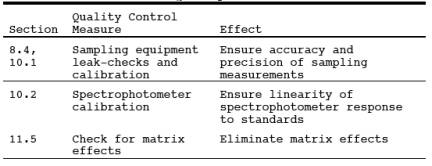
9.0 Quality Control.
9.1 Miscellaneous
Quality Control Measures. Section
9.2 Volume Metering
System Checks. Same as Method 5, Section 9.2.
10.0 Calibration and Standardizations.
NOTE: Maintain a laboratory log of all calibrations.
10.1 Sampling
Equipment. Same as Method 5, Section 10.0.
10.2.1 Measure the
absorbance of the standard solutions using the instrument settings recommended
by the spectrophotometer manufacturer. Repeat until good agreement (±3 percent)
is obtained between two consecutive readings. Plot the absorbance (y-axis)
versus concentration in µg Pb/ml (x-axis). Draw or compute a straight line
through the linear portion of the curve. Do not force the calibration curve
through zero, but if the curve does not pass through the origin or at least lie
closer to the origin than ±0.003 absorbance units, check for incorrectly
prepared standards and for curvature in the calibration curve.
10.2.2 To determine
stability of the calibration curve, run a blank and a standard after every five
samples, and recalibrate as necessary.
11.0 Analytical Procedures.
11.1 Sample Loss Check.
Prior to analysis,
check the liquid level in Containers Number 2 and Number 4. Note on the
analytical data sheet whether leakage occurred during transport. If a
noticeable amount of leakage occurred, either void the sample or take steps,
subject to the approval of the Administrator, to adjust the final results.
11.2 Sample Preparation.
11.2.1 Container No.
1 (Filter). Cut the filter into strips and transfer the strips and all loose
particulate matter into a 125-ml Erlenmeyer flask. Rinse the Petri dish with 10
ml of 50 percent HNO3
to ensure a quantitative transfer,
and add to the flask.
NOTE: If the total volume required in Section 11.2.3
is expected to exceed 80 ml, use a 250-ml flask in place of the 125-ml flask.
11.2.2 Containers No.
2 and No. 4 (Probe and Impingers). Combine the contents of Containers No. 2 and
No. 4, and evaporate to dryness on a hot plate.
11.2.3 Sample Extraction
for Lead.
11.2.3.1 Based on the
approximate stack gas particulate concentration and the total volume of stack
gas sampled, estimate the total weight of particulate sample collected. Next,
transfer the residue from Containers No. 2 and No. 4 to the 125-ml Erlenmeyer
flask that contains the sampling filter using a rubber policeman and 10 ml of
50 percent HNO3 for every 100 mg of sample collected in the
train or a minimum of 30 ml of 50 percent HNO3,
whichever is larger.
11.2.3.2 Place the
Erlenmeyer flask on a hot plate, and heat with periodic stirring for 30 minutes
at a temperature just below boiling. If the sample volume falls below 15 ml,
add more 50 percent HNO3. Add 10 ml of 3 percent H2O2, and continue heating for 10 minutes. Add 50 ml
of hot (80˚C, 176˚F) water, and heat for 20 minutes. Remove the flask from the
hot plate, and allow to cool. Filter the sample through a Millipore membrane
filter, or equivalent, and transfer the filtrate to a 250-ml volumetric flask.
Dilute to volume with water.
11.2.4 Filter Blank.
Cut each filter into strips, and place each filter in a separate 125-ml
Erlenmeyer flask. Add 15 ml of 50 percent HNO3,
and treat as described in Section 11.2.3 using 10 ml of 3 percent H2O2 and 50 ml of hot water. Filter and dilute to a
total volume of 100 ml using water.
11.2.5 Nitric Acid
Blank, 0.1 N. Take the entire 200 ml of 0.1 N HNO3 to
dryness on a steam bath, add 15 ml of 50 percent HNO3, and treat as described in Section 11.2.3 using 10 ml of 3 percent
H202 and 50 ml of hot water.
Dilute to a total volume of 100 ml using water.
11.3 Spectrophotometer Preparation.
Turn on the power;
set the wavelength, slit width, and lamp current; and adjust the background
corrector as instructed by the manufacturer's manual for the particular atomic
absorption spectrophotometer. Adjust the burner and flame characteristics as
necessary.
11.4 Analysis.
11.4.1 Lead
Determination. Calibrate the spectrophotometer as outlined in Section 10.2, and determine the absorbance for each
source sample, the filter blank, and 0.1 N HNO3 blank.
Analyze each sample three times in this manner. Make appropriate dilutions, as
needed, to bring all sample Pb concentrations into the linear absorbance range
of the spectrophotometer. Because instruments vary between manufacturers, no
detailed operating instructions will be given here. Instead, the instructions
provided with the particular instrument should be followed. If the Pb
concentration of a sample is at the low end of the calibration curve and high
accuracy is required, the sample can be taken to dryness on a hot plate and the
residue dissolved in the appropriate volume of water to bring it into the
optimum range of the calibration curve.
11.4.2
Container No. 3 (Silica Gel). This step may be conducted in the field. Weigh
the spent silica gel (or silica gel plus impinger) to the nearest 0.5 g; record
this weight.
11.5 Check for Matrix Effects.
Use the Method of
Standard Additions as follows to check at least one sample from each source for
matrix effects on the Pb results:
11.5.1 Add or spike
an equal volume of standard solution to an aliquot of the sample solution.
11.5.2 Measure the
absorbance of the resulting solution and the absorbance of an aliquot of
unspiked sample.
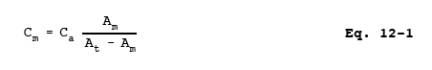
11.5.3 Calculate the
Pb concentration Cm
in µg/ml of the sample solution
using Equation 12-1 in Section 12.5. Volume
corrections will not be required if the solutions as analyzed have been made to
the same final volume. Therefore, Cm and Ca represent Pb concentration before dilutions. Method of Standard
Additions procedures described on pages 9-4 and 9-5 of the section entitled
"General Information" of the Perkin Elmer Corporation Atomic
Absorption Spectrophotometry Manual, Number 303-0152 (Reference 1 in Section 17.0) may also be used. In any event, if the
results of the Method of Standard Additions procedure used on the single source
sample do not agree to within ±5 percent of the value obtained by the routine
atomic absorption analysis, then reanalyze all samples from the source using
the Method of Standard Additions procedure.
12.0 Data Analysis and Calculations.
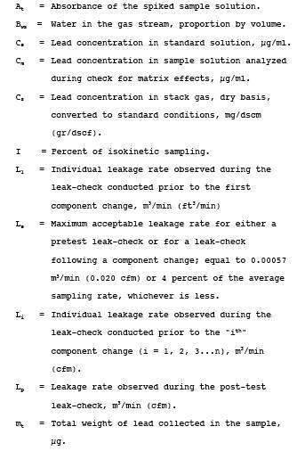
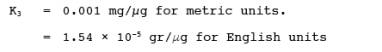
12.1 Nomenclature.
![]()
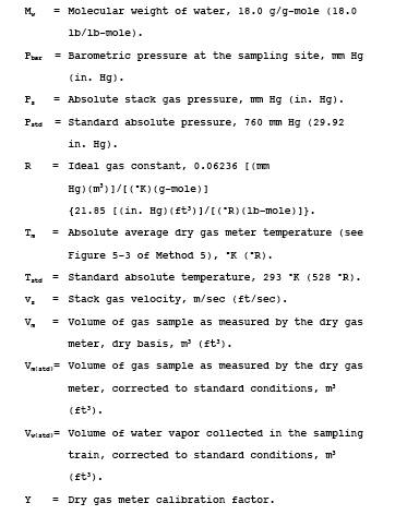
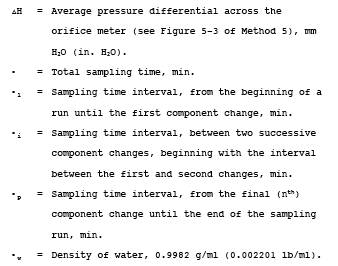
12.2 Average Dry Gas
Meter Temperatures (Tm) and Average Orifice Pressure Drop (∆H). See
data sheet (Figure 5-3 of Method 5).
12.3 Dry Gas Volume,
Volume of Water Vapor, and Moisture Content. Using data obtained in this test,
calculate Vm(std), Vw(std), and
Bws according to the procedures outlined in Method 5, Sections 12.3 through 12.5.
12.4 Total Lead in
Source Sample. For each source sample, correct the average absorbance for the
contribution of the filter blank and the 0.1 N HNO3 blank. Use the calibration curve and this corrected absorbance to determine
the Pb concentration in the sample aspirated into the spectrophotometer.
Calculate the total Pb content mt (in µg) in the
original source sample; correct for all the dilutions that were made to bring
the Pb concentration of the sample into the linear range of the
spectrophotometer.
12.5
Sample Lead Concentration. Calculate the Pb concentration of the sample using
the following equation:
12.6 Lead
Concentration. Calculate the stack gas Pb concentration Cs using Equation 12-2:
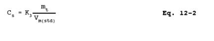
where:
12.7 Stack Gas
Velocity and Volumetric Flow Rate. Calculate the average stack gas velocity and
volumetric flow rate using data obtained in this method and the equations in Sections 12.2 and 12.3 of Method 2.
12.8 Isokinetic
Variation. Same as Method 5, Section 12.11.
13.0 Method Performance.
13.1 Precision.
The within-laboratory
precision, as measured by the coefficient of variation, ranges from 0.2 to 9.5
percent relative to a run-mean concentration. These values were based on tests
conducted at a gray iron foundry, a lead storage battery manufacturing plant, a
secondary lead smelter, and a lead recovery furnace of an alkyl lead
manufacturing plant. The concentrations encountered during these tests ranged
from 0.61 to 123.3 mg Pb/m3.
13.2 Analytical Range.
For a minimum
analytical accuracy of ±10 percent, the lower limit of the range is 100 µg. The
upper limit can be extended considerably by dilution.
13.3 Analytical Sensitivity.
Typical sensitivities
for a 1-percent change in absorption (0.0044 absorbance units) are 0.2 and 0.5
µg Pb/ml for the 217.0 and 283.3 nm lines, respectively.
14.0 Pollution Prevention. [Reserved]
15.0 Waste Management. [Reserved]
16.0 Alternative Procedures.
16.1 Simultaneous Determination of Particulate and Lead Emissions.
Method 5 may be used
to simultaneously determine Pb provided: (1) acetone is used to remove
particulate from the probe and inside of the filter holder as specified by
Method 5, (2) 0.1 N HNO3
is used in the impingers, (3) a
glass fiber filter with a low Pb background is used, and (4) the entire train
contents, including the impingers, are treated and analyzed for Pb as described
in Sections 8.0 and 11.0 of this
method.
16.2 Filter Location.
A filter may be used
between the third and fourth impingers provided the filter is included in the
analysis for Pb.
16.3 In-Stack Filter.
An in-stack filter
may be used provided: (1) a glass-lined probe and at least two impingers, each
containing 100 ml of 0.1 N HNO3 after the in-stack
filter, are used and (2) the probe and impinger contents are recovered and
analyzed for Pb. Recover sample from the nozzle with acetone if a particulate
analysis is to be made.
17.0 References.
Same
as Method 5, Section 17.0, References 2, 3, 4,
5, and 7, with the addition of the following:
1. Perkin Elmer
Corporation. Analytical Methods for Atomic Absorption Spectrophotometry.
Norwalk, Connecticut. September 1976.
2. American Society
for Testing and Materials. Annual Book of ASTM Standards, Part 31: Water,
Atmospheric Analysis. Philadelphia, PA 1974. p. 40-42.
3. Kelin, R., and C.
Hach. Standard Additions—Uses and Limitations in Spectrophotometric Analysis.
Amer. Lab. 9:21-27. 1977.
4. Mitchell, W.J.,
and M.R. Midgett. Determining Inorganic and Alkyl Lead Emissions from
Stationary Sources. U.S. Environmental Protection Agency. Emission Monitoring
and Support Laboratory. Research Triangle Park, NC. (Presented at National APCA
Meeting, Houston. June 26, 1978).
18.0 Tables, Diagrams, Flowcharts, and Validation Data.
Figure
12-1. Inorganic Lead Sampling Train.