Method 308--Procedure for Determination of Methanol Emission from Stationary Sources
Appendix A of part 63 is amended by adding Method 308 in numerical order to read as follows:
Appendix
A to Part 63--Test Methods
8.1.1 Preparation of
Collection Train.
9.1 Miscellaneous
Quality Control Measures.
9.4 Audit Sample
Availability.
10.0 Calibration and
Standardization.
10.1.2 Posttest
Calibration Check.
10.2.2 Continuing
Calibration.
11.1 Gas Chromatograph
Operating Conditions.
11.3 Silica Gel
Adsorbent Sample.
12.0 Data Analysis and
Calculations.
13.0 Method
Performance. [Reserved]
14.0 Pollution
Prevention. [Reserved]
15.0 Waste Management.
[Reserved]
17.0 Tables, Diagrams,
Flowcharts, and Validation Data. [Reserved]
1.0 Scope and Application.
1.1 Analyte.
Methanol. Chemical
Abstract Service (CAS) No. 67-56-1.
1.2 Applicability.
This method applies
to the measurement of methanol emissions from specified stationary sources.
2.0 Summary of Method.
A gas sample is
extracted from the sampling point in the stack. The methanol is collected in
deionized distilled water and adsorbed on silica gel. The sample is returned to
the laboratory where the methanol in the water fraction is separated from other
organic compounds with a gas chromatograph (GC) and is then measured by a flame
ionization detector (FID). The fraction adsorbed on silica gel is extracted
with an aqueous solution of n-propanol and is then separated and measured by
GC/FID.
3.0 Definitions. [Reserved]
4.0 Interferences. [Reserved]
5.0 Safety.
5.1 Disclaimer. This
method may involve hazardous materials, operations, and equipment. This test
method does not purport to address all of the safety problems associated with
its use. It is the responsibility of the user of this test method to establish
appropriate safety and health practices and to determine the applicability of
regulatory limitations before performing this test method.
5.2 Methanol
Characteristics. Methanol is flammable and a dangerous fire and explosion risk.
It is moderately toxic by ingestion and inhalation.
6.0 Equipment and Supplies.
6.1 Sample Collection.
The following items
are required for sample collection:
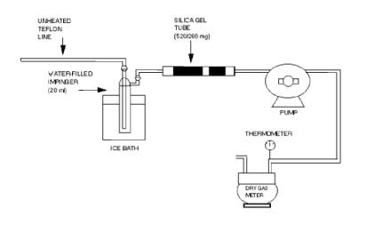
6.1.1 Sampling Train.
The sampling train is shown in Figure 308-1 and component parts are discussed
below.
6.1.1.1 Probe.
Teflon®, approximately 6-millimeter (mm) (0.24 inch) outside diameter.
6.1.1.2 Impinger. A
30-milliliter (ml) midget impinger. The impinger must be connected with
leak-free glass connectors. Silicone grease may not be used to lubricate the
connectors.
6.1.1.3 Adsorbent
Tube. Glass tubes packed with the required amount of the specified adsorbent.
6.1.1.4 Valve. Needle
valve, to regulate sample gas flow rate.
6.1.1.5 Pump.
Leak-free diaphragm pump, or equivalent, to pull gas through the sampling
train. Install a small surge tank between the pump and rate meter to eliminate
the pulsation effect of the diaphragm pump on the rotameter.
6.1.1.6 Rate Meter.
Rotameter, or equivalent, capable of measuring flow rate to within 2 percent of
the selected flow rate of up to 1000 milliliter per minute (ml/min). Alternatively,
the tester may use a critical orifice to set the flow rate.
6.1.1.7 Volume Meter.
Dry gas meter (DGM), sufficiently accurate to measure the sample volume to
within 2 percent, calibrated at the selected flow rate and conditions actually
encountered during sampling, and equipped with a temperature sensor (dial
thermometer, or equivalent) capable of measuring temperature accurately to
within 3 °C (5.4 °F).
6.1.1.8 Barometer.
Mercury (Hg), aneroid, or other barometer capable of measuring atmospheric
pressure to within 2.5 mm (0.1 inch) Hg. See the NOTE in Method 5 (40 CFR part
60, appendix A), section 6.1.2.
6.1.1.9 Vacuum Gauge
and Rotameter. At least 760-mm (30-inch) Hg gauge and 0- to 40-ml/min
rotameter, to be used for leak-check of the sampling train.
6.2 Sample Recovery.
The following items
are required for sample recovery:
6.2.1 Wash Bottles.
Polyethylene or glass, 500-ml, two.
6.2.2 Sample Vials.
Glass, 40-ml, with Teflon®-lined septa, to store impinger samples (one per
sample).
6.2.3 Graduated
Cylinder. 100-ml size.
6.3 Analysis.
The following are
required for analysis:
6.3.1 Gas
Chromatograph. GC with an FID, programmable temperature control, and heated
liquid injection port.
6.3.2 Pump. Capable
of pumping 100 ml/min. For flushing sample loop.
6.3.3 Flow Meter. To
monitor accurately sample loop flow rate of 100 ml/min.
6.3.4 Regulators.
Two-stage regulators used on gas cylinders for GC and for cylinder standards.
6.3.5 Recorder. To
record, integrate, and store chromatograms.
6.3.6 Syringes. 1.0-
and 10-microliter (l) size, calibrated, for injecting samples.
6.3.7 Tubing
Fittings. Stainless steel, to plumb GC and gas cylinders.
6.3.8 Vials. Two
5.0-ml glass vials with screw caps fitted with Teflon®-lined septa for each
sample.
6.3.9 Pipettes.
Volumetric type, assorted sizes for preparing calibration standards.
6.3.10 Volumetric
Flasks. Assorted sizes for preparing calibration standards.
6.3.11 Vials. Glass
40-ml with Teflon®-lined septa, to store calibration standards (one per
standard).
7.0 Reagents and Standards.
NOTE: Unless
otherwise indicated, all reagents must conform to the specifications
established by the Committee on Analytical Reagents of the American Chemical
Society. Where such specifications are not available, use the best available
grade.
7.1 Sampling.
The following are
required for sampling:
7.1.1 Water.
Deionized distilled to conform to the American Society for Testing and
Materials (ASTM) Specification D 1193-77, Type 3. At the option of the analyst,
the potassium permanganate (KMnO4) test for oxidizable organic matter may be
omitted when high concentrations of organic matter are not expected to be
present.
7.1.2 Silica Gel.
Deactivated chromatographic grade 20/40 mesh silica gel packed in glass adsorbent
tubes. The silica gel is packed in two sections. The front section contains 520
milligrams (mg) of silica gel, and the back section contains 260 mg.
7.2 Analysis.
The following are
required for analysis:
7.2.1 Water. Same as
specified in section 7.1.1.
7.2.2 n-Propanol, 3
Percent. Mix 3 ml of n-propanol with 97 ml of water.
7.2.3 Methanol Stock
Standard. Prepare a methanol stock standard by weighing 1 gram of methanol into
a 100-ml volumetric flask. Dilute to 100 ml with water.
7.2.3.1 Methanol Working
Standard. Prepare a methanol working standard by pipetting 1 ml of the methanol
stock standard into a 100-ml volumetric flask. Dilute the solution to 100 ml
with water.
7.2.3.2 Methanol
Standards For Impinger Samples. Prepare a series of methanol standards by
pipetting 1, 2, 5, 10, and 25 ml of methanol working standard solution
respectively into five 50-ml volumetric flasks. Dilute the solutions to 50 ml
with water. These standards will have 2, 4, 10, 20, and 50 µg/ml of methanol,
respectively. After preparation, transfer the solutions to 40-ml glass vials
capped with Teflon® septa and store the vials under refrigeration. Discard any
excess solution.
7.2.3.3 Methanol
Standards for Adsorbent Tube Samples. Prepare a series of methanol standards by
first pipetting 10 ml of the methanol working standard into a 100-ml volumetric
flask and diluting the contents to exactly 100 ml with 3 percent n-propanol
solution. This standard will contain 10 µg/ml of methanol. Pipette 5, 15, and
25 ml of this standard, respectively, into four 50-ml volumetric flasks. Dilute
each solution to 50 ml with 3 percent n-propanol solution. These standards will
have 1, 3, and 5 µg/ml of methanol, respectively. Transfer all four standards
into 40-ml glass vials capped with Teflon®-lined septa and store under
refrigeration. Discard any excess solution.
7.2.4 GC Column.
Capillary column, 30 meters (100 feet) long with an inside diameter (ID) of
0.53 mm (0.02 inch), coated with DB 624 to a film thickness of 3.0 micrometers,
(µm) or an equivalent column. Alternatively, a 30-meter capillary column coated
with polyethylene glycol to a film thickness of 1 µm such as AT-WAX or its
equivalent.
7.2.5 Helium. Ultra
high purity.
7.2.6 Hydrogen. Zero
grade.
7.2.7 Oxygen. Zero
grade.
8.0 Procedure.
8.1 Sampling.
The following items
are required for sampling:
8.1.1 Preparation of Collection Train.
Measure 20 ml of
water into the midget impinger. The adsorbent tube must contain 520 mg of
silica gel in the front section and 260 mg of silica gel in the backup section.
Assemble the train as shown in Figure 308-1. An optional, second impinger that
is left empty may be placed in front of the water-containing impinger to act as
a condensate trap. Place crushed ice and water around the impinger.
Figure 308.1.
Sampling train schematic
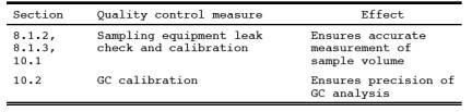
8.1.2 Leak Check.
A leak check prior to
the sampling run is optional; however, a leak check after the sampling run is
mandatory. The leak-check procedure is as follows: Temporarily attach a
suitable (e.g., 0- to 40-ml/min) rotameter to the outlet of the DGM, and place
a vacuum gauge at or near the probe inlet. Plug the probe inlet, pull a vacuum
of at least 250 mm (10 inch) Hg, and note the flow rate as indicated by the
rotameter. A leakage rate not in excess of 2 percent of the average sampling
rate is acceptable. NOTE: Carefully release the probe inlet plug before turning
off the pump.
8.1.3 Sample Collection.
Record the initial
DGM reading and barometric pressure. To begin sampling, position the tip of the
Teflon® tubing at the sampling point, connect the tubing to the impinger, and
start the pump. Adjust the sample flow to a constant rate between 200 and 1000
ml/min as indicated by the rotameter. Maintain this constant rate (±10 percent)
during the entire sampling run. Take readings (DGM, temperatures at DGM and at
impinger outlet, and rate meter) at least every 5 minutes. Add more ice during
the run to keep the temperature of the gases leaving the last impinger at 20 °C
(68 °F) or less. At the conclusion of each run, turn off the pump, remove the
Teflon® tubing from the stack, and record the final readings. Conduct a leak
check as in section 8.1.2. (This leak check is mandatory.) If a leak is found,
void the test run or use procedures acceptable to the Administrator to adjust
the sample volume for the leakage.
8.2 Sample Recovery.
The following items
are required for sample recovery:
8.2.1 Impinger.
Disconnect the impinger. Pour the contents of the midget impinger into a
graduated cylinder. Rinse the midget impinger and the connecting tubes with
water, and add the rinses to the graduated cylinder. Record the sample volume.
Transfer the sample to a glass vial and cap with a Teflon® septum. Discard any
excess sample. Place the samples in an ice chest for shipment to the
laboratory.
8.2.2. Adsorbent
Tubes. Seal the silica gel adsorbent tubes and place them in an ice chest for
shipment to the laboratory.
9.0 Quality Control.
9.1 Miscellaneous Quality Control Measures.
The following quality
control measures are required:
9.2 Applicability.
When the method is
used to analyze samples to demonstrate compliance with a source emission
regulation, an audit sample must be analyzed, subject to availability.
9.3 Audit Procedure.
Analyze an audit
sample with each set of compliance samples. Concurrently analyze the audit
sample and a set of compliance samples in the same manner to evaluate the
technique of the analyst and the standards preparation. The same analyst,
analytical reagents, and analytical system shall be used both for the
compliance samples and the EPA audit sample.
9.4 Audit Sample Availability.
Audit samples will be
supplied only to enforcement agencies for compliance tests. Audit samples may
be obtained by writing:
Source Test Audit
Coordinator (MD-77B)
Air Measurement
Research Division
National Exposure
Research Laboratory
U.S. Environmental
Protection Agency
Research Triangle
Park, NC 27711
or by calling the
Source Test Audit Coordinator (STAC) at (919) 541-7834. The audit sample
request must be made at least 30 days prior to the scheduled compliance sample
analysis.
9.5 Audit Results.
Calculate the audit
sample concentration according to the calculation procedure provided in the
audit instructions included with the audit sample. Fill in the audit sample
concentration and the analyst's name on the audit response form included with
the audit instructions. Send one copy to the EPA Regional Office or the
appropriate enforcement agency and a second copy to the STAC. The EPA Regional
office or the appropriate enforcement agency will report the results of the
audit to the laboratory being audited. Include this response with the results
of the compliance samples in relevant reports to the EPA Regional Office or the
appropriate enforcement agency.
10.0 Calibration and Standardization.
10.1 Metering System.
The following items
are required for the metering system:
10.1.1 Initial Calibration.
10.1.1.1 Before its
initial use in the field, first leak check the metering system (drying tube,
needle valve, pump, rotameter, and DGM) as follows: Place a vacuum gauge at the
inlet to the drying tube, and pull a vacuum of 250 mm (10 inch) Hg; plug or
pinch off the outlet of the flow meter, and then turn off the pump. The vacuum
shall remain stable for at least 30 seconds. Carefully release the vacuum gauge
before releasing the flow meter end.
10.1.1.2 Next, remove
the drying tube, and calibrate the metering system (at the sampling flow rate
specified by the method) as follows: Connect an appropriately sized wet test meter
(e.g., 1 liter per revolution (0.035 cubic feet per revolution)) to the inlet
of the drying tube. Make three independent calibrations runs, using at least
five revolutions of the DGM per run. Calculate the calibration factor, Y (wet
test meter calibration volume divided by the DGM volume, both volumes adjusted
to the same reference temperature and pressure), for each run, and average the
results. If any Y-value deviates by more than 2 percent from the average, the
metering system is unacceptable for use. Otherwise, use the average as the
calibration factor for subsequent test runs.
10.1.2 Posttest Calibration Check.
After each field test
series, conduct a calibration check as in section 10.1.1 above, except for the
following variations: (a) the leak check is not to be conducted, (b) three, or
more revolutions of the DGM may be used, and (c) only two independent runs need
be made. If the calibration factor does not deviate by more than 5 percent from
the initial calibration factor (determined in section 10.1.1), then the DGM
volumes obtained during the test series are acceptable. If the calibration
factor deviates by more than 5 percent, recalibrate the metering system as in
section 10.1.1, and for the calculations, use the calibration factor (initial or
recalibration) that yields the lower gas volume for each test run.
10.1.3 Temperature Sensors.
Calibrate against
mercury-in-glass thermometers.
10.1.4 Rotameter.
The rotameter need
not be calibrated, but should be cleaned and maintained according to the
manufacturer's instruction.
10.1.5 Barometer.
Calibrate against a
mercury barometer.
10.2 Gas Chromatograph.
The following
procedures are required for the gas chromatograph:
10.2.1 Initial Calibration.
Inject 1 µl of each
of the standards prepared in sections 7.2.3.3 and 7.2.3.4 into the GC and
record the response. Repeat the injections for each standard until two
successive injections agree within 5 percent. Using the mean response for each
calibration standard, prepare a linear least squares equation relating the
response to the mass of methanol in the sample. Perform the calibration before
analyzing each set of samples.
10.2.2 Continuing Calibration.
At the beginning of
each day, analyze the mid level calibration standard as described in section
10.5.1. The response from the daily analysis must agree with the response from
the initial calibration within 10 percent. If it does not, the initial
calibration must be repeated.
11.0 Analytical Procedure.
11.1 Gas Chromatograph Operating Conditions.
The following
operating conditions are required for the GC:
11.1.1 Injector.
Configured for capillary column, splitless, 200 °C (392 °F).
11.1.2 Carrier.
Helium at 10 ml/min.
11.1.3 Oven.
Initially at 45 °C for 3 minutes; then raise by 10 °C to 70 °C; then raise by
70 °C/min to 200 °C.
11.2 Impinger Sample.
Inject 1 µl of the
stored sample into the GC. Repeat the injection and average the results. If the
sample response is above that of the highest calibration standard, either
dilute the sample until it is in the measurement range of the calibration line
or prepare additional calibration standards. If the sample response is below
that of the lowest calibration standard, prepare additional calibration
standards. If additional calibration standards are prepared, there shall be at
least two that bracket the response of the sample. These standards should
produce approximately 50 percent and 150 percent of the response of the sample.
11.3 Silica Gel Adsorbent Sample.
The following items
are required for the silica gel adsorbent samples:
11.3.1 Preparation of
Samples. Extract the front and backup sections of the adsorbent tube
separately. With a file, score the glass adsorbent tube in front of the first
section of silica gel. Break the tube open. Remove and discard the glass wool.
Transfer the first section of the silica gel to a 5-ml glass vial and stopper
the vial. Remove the spacer between the first and second section of the
adsorbent tube and discard it. Transfer the second section of silica gel to a separate
5-ml glass vial and stopper the vial.
11.3.2 Desorption of
Samples. Add 3 ml of the 10 percent n-propanol solution to each of the
stoppered vials and shake or vibrate the vials for 30 minutes.
11.3.3 Inject a 1-µl
aliquot of the diluted sample from each vial into the GC. Repeat the injection
and average the results. If the sample response is above that of the highest
calibration standard, either dilute the sample until it is in the measurement
range of the calibration line or prepare additional calibration standards. If
the sample response is below that of the lowest calibration standard, prepare
additional calibration standards. If additional calibration standards are
prepared, there shall be at least two that bracket the response of the sample. These
standards should produce approximately 50 percent and 150 percent of the
response of the sample.
12.0 Data Analysis and Calculations.
12.1 Nomenclature.
Caf = Concentration
of methanol in the front of the adsorbent tube, µg/ml.
Cab = Concentration of
methanol in the back of the adsorbent tube, µg/ml.
Ci = Concentration of
methanol in the impinger portion of the sample train, µg/ml.
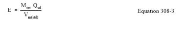
E = Mass emission
rate of methanol, µg/hr (lb/hr).
Mtot = Total mass of
methanol collected in the sample train, µg.
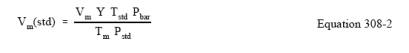
Pbar = Barometric
pressure at the exit orifice of the DGM, mm Hg (in. Hg).
Pstd = Standard
absolute pressure, 760 mm Hg (29.92 in. Hg).
Qstd = Dry volumetric
stack gas flow rate corrected to standard conditions, dscm/hr (dscf/hr).
Tm = Average DGM
absolute temperature, degrees K (°R).
Tstd = Standard
absolute temperature, 293 degrees K (528 °R).
Vaf = Volume of front
half adsorbent sample, ml.
Vab = Volume of back
half adsorbent sample, ml.
Vi = Volume of
impinger sample, ml.
Vm = Dry gas volume
as measured by the DGM, dry cubic meters (dcm), dry cubic feet (dcf).
Vm(std) = Dry gas
volume measured by the DGM, corrected to standard conditions, dry standard
cubic meters (dscm), dry standard cubic feet (dscf).
12.2 Mass of
Methanol. Calculate the total mass of methanol collected in the sampling train
using Equation 308-1.
![]()
12.3 Dry Sample Gas
Volume, Corrected to Standard Conditions. Calculate the volume of gas sampled
at standard conditions using Equation 308-2.
12.4 Mass Emission
Rate of Methanol. Calculate the mass emission rate of methanol using Equation
308-3.
13.0 Method Performance. [Reserved]
14.0 Pollution Prevention. [Reserved]
15.0 Waste Management. [Reserved]
16.0 Bibliography.
1. Rom, J.J.
"Maintenance, Calibration, and Operation of Isokinetic Source Sampling
Equipment." Office of Air Programs, Environmental Protection Agency.
Research Triangle Park, NC. APTD-0576. March 1972.
2. Annual Book of
ASTM Standards. Part 31; Water, Atmospheric Analysis. American Society for
Testing and Materials. Philadelphia, PA. 1974. pp. 40-42.
3. Westlin, P.R. and
R.T. Shigehara. "Procedure for Calibrating and Using Dry Gas Volume Meters
as Calibration Standards." Source Evaluation Society Newsletter.
3(1):17-30. February 1978.
4. Yu, K.K.
"Evaluation of Moisture Effect on Dry Gas Meter Calibration." Source
Evaluation Society Newsletter. 5(1):24-28. February 1980.
5. NIOSH Manual of
Analytical Methods, Volume 2. U.S. Department of Health and Human Services
National Institute for Occupational Safety and Health. Center for Disease
Control. 4676 Columbia Parkway, Cincinnati, OH 45226. (available from the
Superintendent of Documents, Government Printing Office, Washington, DC 20402.)
6. Pinkerton, J.E.
"Method for Measuring Methanol in Pulp Mill Vent Gases." National
Council of the Pulp and Paper Industry for Air and Stream Improvement, Inc.,
New York, NY.
17.0 Tables, Diagrams, Flowcharts, and Validation Data. [Reserved]