METHOD 27 -
DETERMINATION OF VAPOR TIGHTNESS OF GASOLINE DELIVERY TANK USING PRESSURE
VACUUM TEST
3.1 Allowable pressure
change (•p)
3.2 Allowable vacuum
change (•v)
3.5 Delivery tank vapor
collection equipment
3.9 Time period of the
pressure or vacuum test (t)
7.0 Reagents and
Standards. [Reserved]
8.0 Sample Collection,
Preservation, Storage, and Transport.
10.0 Calibration and
Standardization. [Reserved]
11.0 Analytical
Procedures. [Reserved]
12.0 Data Analysis and
Calculations. [Reserved]
14.0 Pollution
Prevention. [Reserved]
15.0 Waste Management.
[Reserved]
18.0 Tables, Diagrams,
Flowcharts, and Validation Data.
[Reserved]
1.0 Scope and Application.
1.1 Applicability. This
method is applicable for the determination of vapor tightness of a gasoline
delivery tank which is equipped with vapor collection equipment.
2.0 Summary of Method.
2.1 Pressure and
vacuum are applied alternately to the compartments of a gasoline delivery tank
and the change in pressure or vacuum is recorded after a specified period of
time.
3.0 Definitions.
3.1 Allowable pressure change (•p)
Means the allowable
amount of decrease in pressure during the static pressure test, within the time
period t, as specified in the appropriate regulation, in mm H2O.
3.2 Allowable vacuum change (•v)
Means the allowable
amount of decrease in vacuum during the static vacuum test, within the time
period t, as specified in the appropriate regulation, in mm H2O.
3.3 Compartment
Means a liquid-tight
division of a delivery tank.
3.4 Delivery tank
Means a container,
including associated pipes and fittings, that is attached to or forms a part of
any truck, trailer, or railcar used for the transport of gasoline.
3.5 Delivery tank vapor collection equipment
Means any piping,
hoses, and devices on the delivery tank used to collect and route gasoline
vapors either from the tank to a bulk terminal vapor control system or from a
bulk plant or service station into the tank.
3.6 Gasoline
Means a petroleum
distillate or petroleum distillate/alcohol blend having a Reid vapor pressure
of 27.6 kilopascals or greater which is used as a fuel for internal combustion
engines.
3.7 Initial pressure (Pi)
Means the pressure
applied to the delivery tank at the beginning of the static pressure test, as
specified in the appropriate regulation, in mm H2O.
3.8 Initial vacuum (Vi)
Means the vacuum
applied to the delivery tank at the beginning of the static vacuum test, as
specified in the appropriate regulation, in mm H2O.
3.9 Time period of the pressure or vacuum test (t)
Means the time period
of the test, as specified in the appropriate regulation, during which the
change in pressure or vacuum is monitored, in minutes.
4.0 Interferences. [Reserved]
5.0 Safety.
5.1 Gasoline contains
several volatile organic compounds (e.g. benzene and hexane) which presents a
potential for fire and/or explosions. It is advisable to take appropriate
precautions when testing a gasoline vessel's vapor tightness, such as
refraining from smoking and using explosion-proof equipment.
5.2 This method may
involve hazardous materials, operations, and equipment. This test method my not
address all of the safety problems associated with its use. It is the
responsibility of the user of this test method to establish appropriate safety
and health practices and determine the applicability of regulatory limitations
prior to performing this test method
6.0 Equipment and Supplies.
The following
equipment and supplies are required for testing:
6.1 Pressure Source.
Pump or compressed gas cylinder of air or inert gas sufficient to pressurize
the delivery tank to 500 mm (20 in.) H2O above
atmospheric pressure.
6.2 Regulator. Low
pressure regulator for controlling pressurization of the delivery tank.
6.3 Vacuum Source.
Vacuum pump capable of evacuating the delivery tank to 250 mm (10 in.) H2O below atmospheric pressure.
6.4 Pressure-Vacuum
Supply Hose.
6.5 Manometer. Liquid
manometer, or equivalent instrument, capable of measuring up to 500 mm (20 in.)
H2O gauge pressure with ± 2.5 mm (0.1 in.) H2O precision.
6.6 Pressure-Vacuum
Relief Valves. The test apparatus shall be equipped with an inline
pressure-vacuum relief valve set to activate at 675 mm (26.6 in.) H2O above atmospheric pressure or 250 mm (10 in.) H2O below atmospheric pressure, with a capacity equal to the
pressurizing or evacuating pumps.
6.7 Test Cap for
Vapor Recovery Hose. This cap shall have a tap for manometer connection and a fitting
with shutoff valve for connection to the pressure-vacuum supply hose.
6.8 Caps for Liquid
Delivery Hoses.
7.0 Reagents and Standards. [Reserved]
8.0 Sample Collection, Preservation, Storage, and Transport.
8.1 Pretest Preparations.
8.1.1 Summary.
Testing problems may occur due to the presence of volatile vapors and/or
temperature fluctuations inside the delivery tank. Under these conditions, it
is often difficult to obtain a stable initial pressure at the beginning of a
test, and erroneous test results may occur. To help prevent this, it is
recommended that prior to testing, volatile vapors be removed from the tank and
the temperature inside the tank be allowed to stabilize. Because it is not
always possible to completely attain these pretest conditions, a provision to
ensure reproducible results is included. The difference in results for two
consecutive runs must meet the criteria in Sections 8.2.2.5 and 8.2.3.5.
8.1.2 Emptying of
Tank. The delivery tank shall be emptied of all liquid.
8.1.3 Purging of
Vapor. As much as possible the delivery tank shall be purged of all volatile
vapors by any safe, acceptable method. One method is to carry a load of
non-volatile liquid fuel, such as diesel or heating oil, immediately prior to
the test, thus flushing out all the volatile gasoline vapors. A second method
is to remove the volatile vapors by blowing ambient air into each tank
compartment for at least 20 minutes. This second method is usually not as
effective and often causes stabilization problems, requiring a much longer time
for stabilization during the testing.
8.1.4 Temperature
Stabilization. As much as possible, the test shall be conducted under
isothermal conditions. The temperature of the delivery tank should be allowed
to equilibrate in the test environment. During the test, the tank should be
protected from extreme environmental and temperature variability, such as
direct sunlight.
8.2 Test Procedure.
8.2.1 Preparations.
8.2.1.1 Open and
close each dome cover.
8.2.1.2 Connect static
electrical ground connections to the tank. Attach the liquid delivery and vapor
return hoses, remove the liquid delivery elbows, and plug the liquid delivery
fittings.
NOTE: The purpose of testing the liquid delivery hoses
is to detect tears or holes that would allow liquid leakage during a delivery.
Liquid delivery hoses are not considered to be possible sources of vapor
leakage, and thus, do not have to be attached for a vapor leakage test.
Instead, a liquid delivery hose could be either visually inspected, or filled
with water to detect any liquid leakage.
8.2.1.3 Attach the
test cap to the end of the vapor recovery hose.
8.2.1.4 Connect the
pressure-vacuum supply hose and the pressure-vacuum relief valve to the
shut-off valve. Attach a manometer to the pressure tap.
8.2.1.5 Connect
compartments of the tank internally to each other if possible. If not possible,
each compartment must be tested separately, as if it were an individual
delivery tank.
8.2.2 Pressure Test.
8.2.2.1 Connect the pressure
source to the pressure vacuum supply hose.
8.2.2.2 Open the
shut-off valve in the vapor recovery hose cap. Apply air pressure slowly,
pressurize the tank to Pi, the initial pressure specified in the
regulation.
8.2.2.3 Close the
shut-off and allow the pressure in the tank to stabilize, adjusting the
pressure if necessary to maintain pressure of Pi.
When the pressure stabilizes, record the time and initial pressure.
8.2.2.4 At the end of
the time period (t) specified in the regulation, record the time and final
pressure.
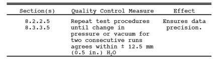
8.2.2.5 Repeat steps
8.2.2.2 through 8.2.2.4 until the change in pressure for two consecutive runs
agrees within 12.5 mm (0.5 in.) H2O.
Calculate the arithmetic average of the two results.
8.2.2.6 Compare the
average measured change in pressure to the allowable pressure change, • p,
specified in the regulation. If the delivery tank does not satisfy the vapor
tightness criterion specified in the regulation, repair the sources of leakage,
and repeat the pressure test until the criterion is met.
8.2.2.7 Disconnect
the pressure source from the pressure-vacuum supply hose, and slowly open the
shut-off valve to bring the tank to atmospheric pressure.
8.2.3 Vacuum Test.
8.2.3.1 Connect the
vacuum source to the pressure vacuum supply hose.
8.2.3.2 Open the
shut-off valve in the vapor recovery hose cap. Slowly evacuate the tank to Vi, the initial vacuum specified in the regulation.
8.2.3.3 Close the
shut-off valve and allow the pressure in the tank to stabilize, adjusting the
pressure if necessary to maintain a vacuum of Vi.
When the pressure stabilizes, record the time and initial vacuum.
8.2.3.4 At the end of
the time period specified in the regulation (t), record the time and final
vacuum.
8.2.3.5 Repeat steps 8.2.3.2
through 8.2.3.4 until the change in vacuum for two consecutive runs agrees
within 12.5 mm (0.5 in.) H2O. Calculate the arithmetic average of the two
results.
8.2.3.6 Compare the
average measured change in vacuum to the allowable vacuum change, • v, as specified in the regulation. If
the delivery tank does not satisfy the vapor tightness criterion specified in
the regulation, repair the sources of leakage, and repeat the vacuum test until
the criterion is met.
8.2.3.7 Disconnect
the vacuum source from the pressure-vacuum supply hose, and slowly open the
shut-off valve to bring the tank to atmospheric pressure.
8.2.4 Post-Test
Clean-up. Disconnect all test equipment and return the delivery tank to its
pretest condition.
9.0 Quality Control.
10.0 Calibration and Standardization. [Reserved]
11.0 Analytical Procedures. [Reserved]
12.0 Data Analysis and Calculations. [Reserved]
13.0 Method Performance.
13.1 Precision. The
vapor tightness of a gasoline delivery tank under positive or negative pressure,
as measured by this method, is precise within 12.5 mm (0.5 in.) H2O.
13.2 Bias. No bias
has been identified.
14.0 Pollution Prevention. [Reserved]
15.0 Waste Management. [Reserved]
16.0 Alternative Procedures.
16.1 The pumping of water
into the bottom of a delivery tank is an acceptable alternative to the pressure
source described above. Likewise, the draining of water out of the bottom of a
delivery tank may be substituted for the vacuum source. Note that some of the
specific step-by-step procedures in the method must be altered slightly to
accommodate these different pressure and vacuum sources.
16.2 Techniques other
than specified above may be used for purging and pressurizing a delivery tank,
if prior approval is obtained from the Administrator. Such approval will be
based upon demonstrated equivalency with the above method.
17.0 References. [Reserved]
18.0 Tables, Diagrams, Flowcharts, and Validation Data. [Reserved]