METHOD
204F--VOLATILE ORGANIC COMPOUNDS CONTENT IN LIQUID INPUT STREAM (DISTILLATION
APPROACH)
4.1.1 Balances/Digital
Scales.
4.1.2 Volume
Measurement Apparatus (Alternative).
4.2 Response Factor
Determination (FIA Technique).
5.3 Calibration and
Other Gases.
5.3.3 FIA Linearity
Calibration Gases.
6.1 Instrument Quality
Control Parameters
7. CALIBRATION AND
STANDARDIZATION
7.1 FIA Calibration and
Linearity Check.
8.1 Determination of
Liquid Input Weight
8.2 Determination of
VOC Content in Input Liquids
8.2.1 Collection of
Liquid Samples.
8.2.3 Preparation of VOC standard bag sample
8.2.4 Determination of VOC response factor
8.2.5 Determination of
coating VOC content as VOC (VIJ).
9. DATA ANALYSIS AND
CALCULATIONS
1. INTRODUCTION
1.1 Applicability.
This procedure
is applicable for determining the input of volatile organic compounds (VOC). It
is intended to be used as a segment in the development of liquid/gas protocols
for determining VOC capture efficiency (CE) for surface coating and printing
operations.
1.2 Principle.
The amount of
VOC introduced to the process (L) is the sum of the products of the weight (W)
of each VOC containing liquid (ink, paint, solvent, etc.) used, and its VOC
content (V), corrected for a response factor (RF).
1.3 Sampling Requirements.
A CE test shall
consist of at least three sampling runs. Each run shall cover at least one
complete production cycle, but shall be at least 3 hours long. The sampling
time for each run need not exceed 8 hours, even if the production cycle has not
been completed. Alternative sampling times may be used with the approval of the
Administrator.
2. SUMMARY OF METHOD
A sample of each
coating used is distilled to separate the VOC fraction. The distillate is used
to prepare a known standard for analysis by an flame ionization analyzer (FIA),
calibrated against propane, to determine its RF.
3. SAFETY
Because this
procedure is often applied in highly explosive areas, caution and care should
be exercised in choosing, installing, and using the appropriate equipment.
4. EQUIPMENT AND SUPPLIES
Mention of trade
names or company products does not constitute endorsement. All gas
concentrations (percent, ppm) are by volume, unless otherwise noted.
4.1 Liquid Weight.
4.1.1 Balances/Digital Scales.
To weigh drums
of VOC containing liquids to within 0.2 lb or 1.0 percent of the total weight
of VOC liquid used.
4.1.2 Volume Measurement Apparatus (Alternative).
Volume meters,
flow meters, density measurement equipment, etc., as needed to achieve the same
accuracy as direct weight measurements.
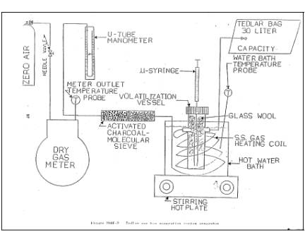
4.2 Response Factor Determination (FIA Technique).
The VOC
distillation system and Tedlar gas bag generation system apparatuses are shown
in Figures 204F-1 and 204F-2, respectively. The following equipment is
required:
4.2.1 Sample
Collection Can. An
appropriately-sized metal can to be used to collect VOC containing materials.
The can must be constructed in such a way that it can be grounded to the
coating container.
4.2.2 Needle
Valves. To control gas
flow.
4.2.3
Regulators. For
calibration, dilution, and sweep gas cylinders.
4.2.4 Tubing
and Fittings. Teflon and
stainless steel tubing and fittings with diameters, lengths, and sizes
determined by the connection requirements of the equipment.
4.2.5
Thermometer. Capable of
measuring the temperature of the hot water and oil baths to within 1°C.
4.2.6
Analytical Balance. To
measure ±0.01 mg.
4.2.7
Microliter Syringe. 10-µl
size.
4.2.8 Vacuum
Gauge or Manometer. 0- to
760-mm (0- to 30-in.) Hg U-Tube manometer or vacuum gauge.
4.2.9 Hot Oil
Bath, With Stirring Hot Plate. Capable
of heating and maintaining a distillation vessel at 110 ± 3°C.
4.2.10 Ice
Water Bath. To cool the
distillation flask.
4.2.11
Vacuum/Water Aspirator. A
device capable of drawing a vacuum to within 20 mm Hg from absolute.
4.2.12 Rotary
Evaporator System. Complete
with folded inner coil, vertical style condenser, rotary speed control, and
Teflon sweep gas delivery tube with valved inlet. Buchi Rotavapor or
equivalent.
4.2.13
Ethylene Glycol Cooling/Circulating Bath. Capable of maintaining the condenser coil fluid at -10°C.
4.2.14 Dry
Gas Meter (DGM). Capable
of measuring the dilution gas volume within 2 percent, calibrated with a
spirometer or bubble meter, and equipped with a temperature gauge capable of
measuring temperature within 3°C.
4.2.15
Activated Charcoal/Mole Sieve Trap. To
remove any trace level of organics picked up from the DGM.
4.2.16 Gas
Coil Heater. Sufficient
length of 0.125-inch stainless steel tubing to allow heating of the dilution
gas to near the water bath temperature before entering the volatilization
vessel.
4.2.17 Water
Bath, With Stirring Hot Plate. Capable
of heating and maintaining a volatilization vessel and coil heater at a
temperature of 100 ± 5°C.
4.2.18
Volatilization Vessel. 50-ml
midget impinger fitted with a septum top and loosely filled with glass wool to
increase the volatilization surface.
4.2.19 Tedlar
Gas Bag. Capable of
holding 30 liters of gas, flushed clean with zero air, leak tested, and
evacuated.
4.2.20
Organic Concentration Analyzer. An
FIA with a span value of 1.5 times the expected concentration as propane;
however, other span values may be used if it can be demonstrated that they
would provide equally accurate measurements. The FIA instrument should be the
same instrument used in the gaseous analyses adjusted with the same fuel,
combustion air, and sample back-pressure (flow rate) settings. The system shall
be capable of meeting or exceeding the following specifications:
4.2.20.1 Zero
Drift. Less than ±3.0
percent of the span value.
4.2.20.2
Calibration Drift. Less
than ±3.0 percent of the span value.
4.2.20.3
Calibration Error. Less
than ±3.0 percent of the calibration gas value.
4.2.21
Integrator/Data Acquisition System. An
analog or digital device or computerized data acquisition system used to
integrate the FIA response or compute the average response and record
measurement data. The minimum data sampling frequency for computing average or
integrated value is one measurement value every 5 seconds. The device shall be
capable of recording average values at least once per minute.
4.2.22 Chart
Recorder (Optional). A
chart recorder or similar device is recommended to provide a continuous analog
display of the measurement results during the liquid sample analysis.
5. REAGENTS AND STANDARDS
5.1 Zero Air.
High purity air
with less than 1 ppm of organic material (as propane) or less than 0.1 percent
of the span value, whichever is greater. Used to supply dilution air for making
the Tedlar bag gas samples.
5.2 THC Free N 2.
High purity N2 with less than 1 ppm THC. Used as sweep gas
in the rotary evaporator system.
5.3 Calibration and Other Gases.
Gases used for
calibration, fuel, and combustion air (if required) are contained in compressed
gas cylinders. All calibration gases shall be traceable to National Institute
of Standards and Technology standards and shall be certified by the
manufacturer to ±1 percent of the tag value. Additionally, the manufacturer of
the cylinder should provide a recommended shelf life for each calibration gas
cylinder over which the concentration does not change more than ±2 percent from
the certified value. For calibration gas values not generally available,
dilution systems calibrated using Method 205 may be used. Alternative methods
for preparing calibration gas mixtures may be used with the approval of the
Administrator.
5.3.1 Fuel.
The FIA
manufacturer's recommended fuel should be used. A 40 percent H2/60 percent He, or 40 percent H2/60 percent N2 mixture
is recommended to avoid fuels with oxygen to avoid an oxygen synergism effect that
reportedly occurs when oxygen concentration varies significantly from a mean
value. Other mixtures may be used provided the tester can demonstrate to the
Administrator that there is no oxygen synergism effect.
5.3.2 Combustion Air.
High purity air
with less than 1 ppm of organic material (as propane) or less than 0.1 percent
of the span value, whichever is greater.
5.3.3 FIA Linearity Calibration Gases.
Low-, mid-, and
high-range gas mixture standards with nominal propane concentration of 20-30,
45-55, and 70-80 percent of the span value in air, respectively. Other
calibration values and other span values may be used if it can be shown that
equally accurate measurements would be achieved.
5.3.4 System Calibration Gas.
Gas mixture
standard containing propane in air, approximating the VOC concentration
expected for the Tedlar gas bag samples.
6. QUALITY CONTROL
6.1 Instrument Quality Control Parameters
Required
instrument quality control parameters are found in the following sections:
6.1.1 The FIA system must be calibrated as
specified in section 7.1.
6.1.2 The system drift check must be performed as
specified in section 7.2.
6.2 Precision Control.
A minimum of one
sample in each batch must be distilled and analyzed in duplicate as a precision
control. If the results of the two analyses differ by more than +10 percent of
the mean, then the system must be reevaluated and the entire batch must be
redistilled and analyzed.
6.3 Audits.
6.3.1 Audit Procedure.
Concurrently,
analyze the audit sample and a set of compliance samples in the same manner to
evaluate the technique of the analyst and the standards preparation. The same
analyst, analytical reagents, and analytical system shall be used both for
compliance samples and the EPA audit sample. If this condition is met, auditing
of subsequent compliance analyses for the same enforcement agency within 30
days is not required. An audit sample set may not be used to validate different
sets of compliance samples under the jurisdiction of different enforcement
agencies, unless prior arrangements are made with both enforcement agencies.
6.3.2 Audit Samples.
Audit Sample
Availability. Audit samples will be supplied only to enforcement agencies for
compliance tests. The availability of audit samples may be obtained by writing:
Source Test
Audit Coordinator (STAC) (MD-77B)
Quality
Assurance Division
Atmospheric
Research and Exposure Assessment Laboratory
U.S.
Environmental Protection Agency
Research
Triangle Park, NC 27711
or by calling
the STAC at (919) 541-7834. The request for the audit sample must be made at
least 30 days prior to the scheduled compliance sample analysis.
6.3.3 Audit Results.
Calculate the
audit sample concentration according to the calculation procedure described in
the audit instructions included with the audit sample. Fill in the audit sample
concentration and the analyst's name on the audit response form included with
the audit instructions. Send one copy to the EPA Regional Office or the
appropriate enforcement agency, and a second copy to the STAC. The EPA Regional
Office or the appropriate enforcement agency will report the results of the
audit to the laboratory being audited. Include this response with the results
of the compliance samples in relevant reports to the EPA Regional Office or the
appropriate enforcement agency.
7. CALIBRATION AND STANDARDIZATION
7.1 FIA Calibration and Linearity Check.
Make necessary
adjustments to the air and fuel supplies for the FIA and ignite the burner.
Allow the FIA to warm up for the period recommended by the manufacturer. Inject
a calibration gas into the measurement system and adjust the back-pressure
regulator to the value required to achieve the flow rates specified by the
manufacturer. Inject the zero- and the high-range calibration gases and adjust
the analyzer calibration to provide the proper responses. Inject the low- and
mid-range gases and record the responses of the measurement system. The
calibration and linearity of the system are acceptable if the responses for all
four gases are within 5 percent of the respective gas values. If the
performance of the system is not acceptable, repair or adjust the system and
repeat the linearity check. Conduct a calibration and linearity check after
assembling the analysis system and after a major change is made to the system.
A calibration curve consisting of zero gas and two calibration levels must be
performed at the beginning and end of each batch of samples.
7.2 Systems Drift Checks.
After each
sample, repeat the system calibration checks in section 7.1 before any
adjustments to the FIA or measurement system are made. If the zero or
calibration drift exceeds ±3 percent of the span value, discard the result and
repeat the analysis. Alternatively, recalibrate the FIA as in section 7.1 and report
the results using both sets of calibration data (i.e., data determined prior to
the test period and data determined following the test period). The data that
results in the lowest CE value shall be reported as the results for the test
run.
8. PROCEDURES
8.1 Determination of Liquid Input Weight
8.1.1 Weight Difference.
Determine the
amount of material introduced to the process as the weight difference of the
feed material before and after each sampling run. In determining the total VOC
containing liquid usage, account for: (a) the initial (beginning) VOC
containing liquid mixture; (b) any solvent added during the test run; (c) any
coating added during the test run; and (d) any residual VOC containing liquid
mixture remaining at the end of the sample run.
8.1.1.1 Identify all points where VOC containing
liquids are introduced to the process. To obtain an accurate measurement of VOC
containing liquids, start with an empty fountain (if applicable). After
completing the run, drain the liquid in the fountain back into the liquid drum
(if possible), and weigh the drum again. Weigh the VOC containing liquids to
±0.5 percent of the total weight (full) or ±1.0 percent of the total weight of
VOC containing liquid used during the sample run, whichever is less. If the
residual liquid cannot be returned to the drum, drain the fountain into a
preweighed empty drum to determine the final weight of the liquid.
8.1.1.2 If it is not possible to measure a single
representative mixture, then weigh the various components separately (e.g., if
solvent is added during the sampling run, weigh the solvent before it is added
to the mixture). If a fresh drum of VOC containing liquid is needed during the
run, then weigh both the empty drum and fresh drum.
8.1.2 Volume
Measurement (Alternative).
If direct weight
measurements are not feasible, the tester may use volume meters and flow rate
meters (and density measurements) to determine the weight of liquids used if it
can be demonstrated that the technique produces results equivalent to the
direct weight measurements. If a single representative mixture cannot be
measured, measure the components separately.
8.2 Determination of VOC Content in Input Liquids
8.2.1 Collection of Liquid Samples.
8.2.1.1 Collect a 1-pint or larger sample of the
VOC containing liquid mixture at each application location at the beginning and
end of each test run. A separate sample should be taken of each VOC containing
liquid added to the application mixture during the test run. If a fresh drum is
needed during the sampling run, then obtain a sample from the fresh drum.
8.2.1.2 When collecting the sample, ground the
sample container to the coating drum. Fill the sample container as close to the
rim as possible to minimize the amount of headspace.
8.2.1.3 After the sample is collected, seal the
container so the sample cannot leak out or evaporate.
8.2.1.4 Label the container to identify clearly the
contents.
8.2.2.1 Assemble the rotary evaporator as shown in
Figure 204F-1.
8.2.2.2 Leak check the rotary evaporation system by
aspirating a vacuum of approximately 20 mm Hg from absolute. Close up the
system and monitor the vacuum for approximately 1 minute. If the vacuum falls
more than 25 mm Hg in 1 minute, repair leaks and repeat. Turn off the aspirator
and vent vacuum.
8.2.2.3 Deposit approximately 20 ml of sample
(inks, paints, etc.) into the rotary evaporation distillation flask.
8.2.2.4 Install the distillation flask on the
rotary evaporator.
8.2.2.5 Immerse the distillate collection flask
into the ice water bath.
8.2.2.6 Start rotating the distillation flask at a
speed of approximately 30 rpm.
8.2.2.7 Begin heating the vessel at a rate of 2 to
3°C per minute.
8.2.2.8 After the hot oil bath has reached a
temperature of 50°C or pressure is evident on the mercury manometer, turn on
the aspirator and gradually apply
a vacuum to the evaporator to within 20 mm Hg of absolute. Care should be taken
to prevent material burping from the distillation flask.
8.2.2.9 Continue heating until a temperature of
110°C is achieved and maintain this temperature for at least 2 minutes, or
until the sample has dried in the distillation
flask.
8.2.2.10 Slowly introduce the N2 sweep gas through the purge tube and into
the distillation flask, taking care to maintain a vacuum of approximately
400-mm Hg from absolute.
8.2.2.11 Continue sweeping the remaining solvent VOC
from the distillation flask and condenser assembly for 2 minutes, or until all
traces of condensed solvent are gone from the vessel. Some distillate may
remain in the still head. This will not affect solvent recovery ratios.
8.2.2.12 Release the vacuum, disassemble the
apparatus and transfer the distillate to a labeled, sealed vial.
8.2.3
Preparation of VOC standard bag sample.
8.2.3.1 Assemble the bag sample generation system
as shown in Figure 204F-2 and bring the water bath up to near boiling
temperature.
8.2.3.2 Inflate the Tedlar bag and perform a leak
check on the bag.
8.2.3.3 Evacuate the bag and close the bag inlet
valve.
8.2.3.4 Record the current barometric pressure.
8.2.3.5 Record the starting reading on the dry gas
meter, open the bag inlet valve, and start the dilution zero air flowing into
the Tedlar bag at approximately 2 liters per minute.
8.2.3.6 The bag sample VOC concentration should be
similar to the gaseous VOC concentration measured in the gas streams. The
amount of liquid VOC required can be approximated using equations in section
9.2. Using Equation 204F-4, calculate CVOC by
assuming RF is 1.0 and selecting the desired gas concentration in terms of
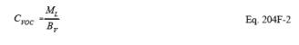
propane, CC3. Assuming BV is
20 liters, ML, the approximate amount of liquid to be
used to prepare the bag gas sample, can be calculated using Equation 204F-2.
8.2.3.7 Quickly withdraw an aliquot of the approximate
amount calculated in section 8.2.3.6 from the distillate vial with the
microliter syringe and record its weight from the analytical balance to the
nearest 0.01 mg.
8.2.3.8 Inject the contents of the syringe through
the septum of the volatilization vessel into the glass wool inside the vessel.
8.2.3.9 Reweigh and record the tare weight of the
now empty syringe.
8.2.3.10 Record the pressure and temperature of the
dilution gas as it is passed through the dry gas meter.
8.2.3.11 After approximately 20 liters of dilution
gas have passed into the Tedlar bag, close the valve to the dilution air source
and record the exact final reading on the dry gas meter.
8.2.3.12 The gas bag is then analyzed by FIA within
1 hour of bag preparation in accordance with the procedure in section 8.2.4.
8.2.4
Determination of VOC response factor.
8.2.4.1 Start up the FIA instrument using the same
settings as used for the gaseous VOC measurements.
8.2.4.2 Perform the FIA analyzer calibration and
linearity checks according to the procedure in section 7.1. Record the
responses to each of the calibration gases and the back-pressure setting of the
FIA.
8.2.4.3 Connect the Tedlar bag sample to the FIA
sample inlet and record the bag concentration in terms of propane. Continue the
analyses until a steady reading is obtained for at least 30 seconds. Record the
final reading and calculate the RF.
8.2.5 Determination of coating VOC content as VOC (VIJ).
8.2.5.1 Determine the VOC content of the coatings
used in the process using EPA Method 24 or 24A as applicable.
9. DATA ANALYSIS AND CALCULATIONS
9.1. Nomenclature
BV = Volume of bag sample volume, liters.
CC3 = Concentration of bag sample as propane,
mg/liter.
CVOC = Concentration of bag sample as VOC,
mg/liter.
K = 0.00183 mg
propane/(liter-ppm propane)
L = Total VOC
content of liquid input, kg propane.
ML = Mass of VOC liquid injected into the bag,
mg.
MV = Volume of gas measured by DGM, liters.
PM = Absolute DGM gas pressure, mm Hg.
PSTD = Standard absolute pressure, 760 mm Hg.
RC3 = FIA reading for bag gas sample, ppm
propane.
RF = Response
factor for VOC in liquid, weight VOC/weight propane.
RFJ = Response factor for VOC in liquid J,
weight VOC/weight propane.
TM = DGM temperature, °K.
TSTD = Standard absolute temperature, 293°K.
VIJ = Initial VOC weight fraction of VOC liquid
J.
VFJ = Final VOC weight fraction of VOC liquid
J.
VAJ = VOC weight fraction of VOC liquid J added
during the run.
WIJ = Weight of VOC containing liquid J at
beginning of run, kg.
WFJ = Weight of VOC containing liquid J at end
of run, kg.
WAJ = Weight of VOC containing liquid J added
during the run, kg.
9.2 Calculations
9.2.1 Bag
sample volume.
![]()
9.2.2 Bag
sample VOC concentration.
9.2.3 Bag
sample VOC concentration as propane.
![]()
9.2.4 Response
Factor.
![]()
9.2.5 Total
VOC Content of the Input VOC Containing Liquid.
![]()
10. DIAGRAMS
Figure 204F-1
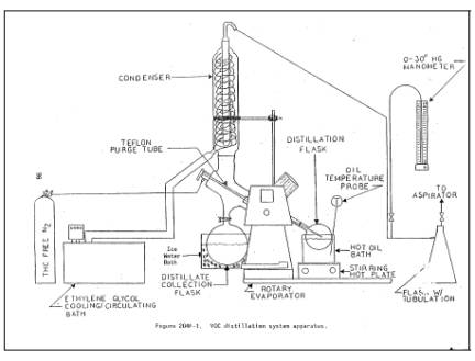
Figure 204F-2