METHOD
204--CRITERIA FOR AND VERIFICATION OF A PERMANENT OR TEMPORARY TOTAL ENCLOSURE
3.1 Natural Draft
Opening (NDO).
3.2 Permanent Total
Enclosure (PE).
3.3 Temporary Total
Enclosure (TTE).
5. CRITERIA FOR
TEMPORARY TOTAL ENCLOSURE
6 CRITERIA FOR A
PERMANENT TOTAL ENCLOSURE
1. SCOPE AND APPLICATION
This procedure
is used to determine whether a permanent or temporary enclosure meets the criteria
for a total enclosure. An existing building may be used as a temporary or
permanent enclosure as long as it meets the appropriate criteria described in
this method.
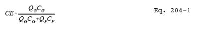
2. SUMMARY OF METHOD
An enclosure is
evaluated against a set of criteria. If the criteria are met and if all the
exhaust gases from the enclosure are ducted to a control device, then the
volatile organic compounds (VOC) capture efficiency (CE) is assumed to be 100
percent, and CE need not be measured. However, if part of the exhaust gas
stream is not ducted to a control device, CE must be determined.
3. DEFINITIONS
3.1 Natural Draft Opening (NDO).
Any permanent
opening in the enclosure that remains open during operation of the facility and
is not connected to a duct in which a fan is installed.
3.2 Permanent Total Enclosure (PE).
A permanently
installed enclosure that completely surrounds a source of emissions such that
all VOC emissions are captured and contained for discharge to a control device.
3.3 Temporary Total Enclosure (TTE).
A temporarily
installed enclosure that completely surrounds a source of emissions such that
all VOC emissions that are not directed through the control device (i.e.
uncaptured) are captured by the enclosure and contained for discharge through
ducts that allow for the accurate measurement of the uncaptured VOC emissions.
3.4 Building Enclosure (BE).
An existing
building that is used as a TTE.
4. SAFETY
An evaluation of
the proposed building materials and the design for the enclosure is recommended
to minimize any potential hazards.
5. CRITERIA FOR TEMPORARY TOTAL ENCLOSURE
5.1 Any NDO shall be at least four equivalent
opening diameters from each VOC emitting point unless otherwise specified by
the Administrator.
5.2 Any exhaust point from the enclosure shall
be at least four equivalent duct or hood diameters from each NDO.
5.3 The total area of all NDO's shall not
exceed 5 percent of the surface area of the enclosure's four walls, floor, and
ceiling.
5.4 The average facial velocity (FV) of air through
all NDO's shall be at least 3,600 m/hr (200 fpm). The direction of air flow
through all NDO's shall be into the enclosure.
5.5 All access doors and windows whose areas
are not included in section 5.3 and are not included in the calculation in section
5.4 shall be closed during routine operation of the process.
6. CRITERIA FOR A PERMANENT TOTAL ENCLOSURE
6.1 Same as sections 5.1 and 5.3 through 5.5.
6.2 All VOC emissions must be captured and
contained for discharge through a control device.
7. QUALITY CONTROL
7.1 The success of this method lies in
designing the TTE to simulate the conditions that exist without the TTE (i.e.,
the effect of the TTE on the normal flow patterns around the affected facility
or the amount of uncaptured VOC emissions should be minimal). The TTE must
enclose the application stations, coating reservoirs, and all areas from the
application station to the oven. The oven does not have to be enclosed if it is
under negative pressure. The NDO's of the temporary enclosure and an exhaust
fan must be properly sized and placed.
7.2 Estimate the ventilation rate of the TTE
that best simulates the conditions that exist without the TTE (i.e., the effect
of the TTE on the normal flow patterns around the affected facility or the
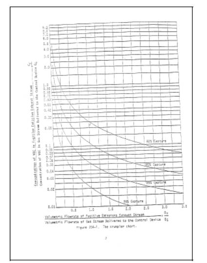
amount of uncaptured VOC emissions should be minimal). Figure
204-1 or the following equation may be used as an aid.
Measure the
concentration (CG) and flow rate (QG) of the captured gas stream, specify a
safe concentration (CF) for the uncaptured gas stream, estimate
the CE, and then use the plot in Figure 204-1 or Equation 204-1 to determine
the volumetric flow rate of the uncaptured gas stream (QF). An exhaust fan that has a variable flow
control is desirable.
7.3 Monitor the VOC concentration of the
captured gas steam in the duct before the capture device without the TTE. To
minimize the effect of temporal variation on the captured emissions, the
baseline measurement should be made over as long a time period as practical. However,
the process conditions must be the same for the measurement in section 7.5 as
they are for this baseline measurement. This may require short measuring times
for this quality control check before and after the construction of the TTE.
7.4 After the TTE is constructed, monitor the
VOC concentration inside the TTE. This concentration should not continue to
increase, and must not exceed the safe level according to Occupational Safety
and Health Administration requirements for permissible exposure limits. An
increase in VOC concentration indicates poor TTE design.
7.5 Monitor the VOC concentration of the
captured gas stream in the duct before the capture device with the TTE. To
limit the effect of the TTE on the process, the VOC concentration with and without
the TTE must be within 10 percent. If the measurements do not agree, adjust the
ventilation rate from the TTE until they agree within 10 percent.
8. PROCEDURE
8.1 Determine the equivalent diameters of the NDO's
and determine the distances from each VOC emitting point to all NDO's.
Determine the equivalent diameter of each exhaust duct or hood and its distance
to all NDO's. Calculate the distances in terms of equivalent diameters. The
number of equivalent diameters shall be at least four.
8.2 Measure the total surface area (AT) of the enclosure and the total area (AN) of all NDO's in the enclosure. Calculate
the NDO to enclosure area ratio (NEAR) as follows:
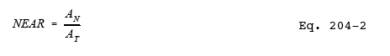
The NEAR must be
< 0.05.
8.3 Measure the volumetric flow rate, corrected
to standard conditions, of each gas stream exiting the enclosure through an
exhaust duct or hood using EPA Method 2. In some
cases (e.g., when the building is the enclosure), it may be necessary to
measure the volumetric flow rate, corrected to standard conditions, of each gas
stream entering the enclosure through a forced makeup air duct using Method 2.
Calculate FV using the following equation:
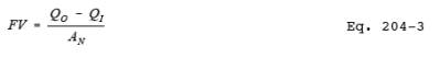
where:
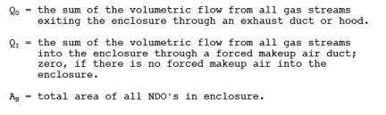
The FV shall be
at least 3,600 m/hr (200 fpm). Alternatively, measure the pressure differential
across the enclosure. A pressure drop of 0.013 mm Hg (0.007 in. H2O) corresponds to an FV of 3,600 m/hr (200
fpm).
8.4 Verify that the direction of air flow
through all NDO's is inward. If FV is less than 9,000 m/hr (500 fpm), the
continuous inward flow of air shall be verified using streamers, smoke tubes,
or tracer gases. Monitor the direction of air flow for at least 1 hour, with
checks made no more than 10 minutes apart. If FV is greater than 9,000 m/hr
(500 fpm), the direction of air flow through the NDOs shall be presumed to be
inward at all times without verification.
9. DIAGRAMS