METHOD 103 - BERYLLIUM SCREENING METHOD
6.2 Measurement of
Stack Conditions.
8.0 Sample Collection,
Preservation, Transport, and Storage.
8.1 Selection of a
Sampling Site and Number of Sample Runs.
8.2 Measurement of
Stack Conditions.
8.3 Preparation of
Sampling Train.
9.0 Quality Control.
[Reserved]
10.0 Calibration and
Standardization.
12.0 Data Analysis and
Calculations.
13.0 Method
Performance. [Reserved]
14.0 Pollution
Prevention. [Reserved]
15.0 Waste Management.
[Reserved]
17.0 Tables, Diagrams,
Flow Charts, and Validation Data.
1.0 Scope and Application.
1.1 Analytes.
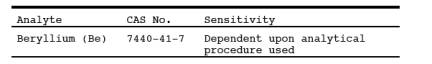
1.2 Applicability.
This procedure
details guidelines and requirements for methods acceptable for use in
determining Be emissions in ducts or stacks at stationary
sources.
1.3 Data Quality Objectives.
Adherence to the
requirements of this method will enhance the quality of the data obtained from
air pollutant sampling methods.
2.0 Summary of Method.
2.1 Particulate Be
emissions are withdrawn isokinetically from three points in a duct or stack and
are collected on a filter. The collected sample is analyzed for Be using an appropriate
technique.
3.0 Definitions. [Reserved]
4.0 Interferences. [Reserved]
5.0 Safety.
5.1 Disclaimer.
This method may
involve hazardous materials, operations, and equipment. This test method may
not address all of the safety problems associated with its use. It is the
responsibility of the user of this test method to establish appropriate safety
and health practices and determine the applicability of regulatory limitations
prior to performing this test method.
5.2 Hydrochloric Acid (HCl).
Highly corrosive and
toxic. Vapors are highly irritating to eyes, skin, nose, and lungs, causing
severe damage. May cause bronchitis, pneumonia, or edema of lungs. Exposure to
concentrations of 0.13 to 0.2 percent can be lethal to humans in a few minutes.
Provide ventilation to limit exposure. Reacts with metals, producing hydrogen
gas. Personal protective equipment and safe procedures are useful in preventing
chemical splashes. If contact occurs, immediately flush with copious amounts of
water at least 15 minutes. Remove clothing under shower and decontaminate.
Treat residual chemical burn as thermal burn.
6.0 Equipment and Supplies.
6.1 Sample Collection.
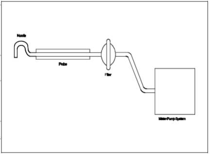
A schematic of the
required sampling train configuration is shown in Figure
103-1 in Section 17.0. The essential components of the train are as
follows:
6.1.1 Nozzle.
Stainless steel, or equivalent, with sharp, tapered leading edge.
6.1.2 Probe. Sheathed
borosilicate or quartz glass tubing.
6.1.3 Filter.
Millipore AA, or equivalent, with appropriate filter holder that provides a
positive seal against leakage from outside or around the filter. It is
suggested that a Whatman 41, or equivalent, be placed immediately against the
back side of the Millipore filter as a guard against breakage of the Millipore.
Include the backup filter in the analysis. To be equivalent, other filters
shall exhibit at least 99.95 percent efficiency (0.05 percent penetration) on
0.3 micron dioctyl phthalate smoke particles, and be amenable to the Be
analysis procedure. The filter efficiency tests shall be conducted in
accordance with ASTM D 2986-71, 78, 95a (incorporated by reference ) see §61.18). Test data from the supplier's
quality control program are sufficient for this purpose.
6.1.4 Meter-Pump
System. Any system that will maintain isokinetic sampling rate, determine
sample volume, and is capable of a sampling rate of greater than 14 lpm
6.2 Measurement of Stack Conditions.
The following
equipment is used to measure stack conditions:
6.2.1 Pitot Tube.
Type S, or equivalent, with a constant coefficient (±5 percent) over the
working range.
6.2.2 Inclined
Manometer, or Equivalent. To measure velocity head to ±10 percent of the
minimum value.
6.2.3 Temperature
Measuring Device. To measure stack temperature to ±1.5 percent of the minimum
absolute stack temperature.
6.2.4 Pressure
Measuring Device. To measure stack pressure to ±2.5 mm Hg (0.1 in. Hg).
6.2.5 Barometer. To
measure atmospheric pressure to ±2.5 mm Hg (0.1 in. Hg).
6.2.6 Wet and Dry
Bulb Thermometers, Drying Tubes, Condensers, or Equivalent. To determine stack
gas moisture content to ±1 percent.
6.3 Sample Recovery.
6.3.1 Probe Cleaning
Equipment. Probe brush or cleaning rod at least as long as probe, or equivalent.
Clean cotton balls, or equivalent, should be used with the rod.
6.3.2 Leakless Glass
Sample Bottles. To contain sample.
6.4 Analysis.
All equipment
necessary to perform an atomic absorption, spectrographic, fluorometric,
chromatographic, or equivalent analysis.
7.0 Reagents and Standards.
7.1 Sample Recovery.
7.1.1 Water.
Deionized distilled, to conform to ASTM D 1193-77, 91 (incorporated by
reference - see §61.18), Type 3.
7.1.2 Acetone.
Reagent grade.
7.1.3 Wash Acid, 50
Percent (V/V) Hydrochloric Acid (HCl). Mix equal volumes of concentrated HCl
and water, being careful to add the acid slowly to the water.
7.2 Analysis.
Reagents and
standards as necessary for the selected analytical procedure.
8.0 Sample Collection, Preservation, Transport, and Storage.
Guidelines for source
testing are detailed in the following sections. These guidelines are generally
applicable; however, most sample sites differ to some degree and temporary
alterations such as stack extensions or expansions often are required to insure
the best possible sample site. Further, since Be is hazardous, care should be
taken to minimize exposure. Finally, since the total quantity of Be to be
collected is quite small, the test must be carefully conducted to prevent
contamination or loss of sample.
8.1 Selection of a Sampling Site and Number of Sample Runs.
Select a suitable
sample site that is as close as practicable to the point of atmospheric
emission. If possible, stacks smaller than one foot in diameter should not be
sampled.
8.1.1 Ideal Sampling
Site. The ideal sampling site is at least eight stack or duct diameters
downstream and two diameters upstream from any flow disturbance such as a bend,
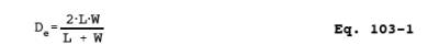
expansion or contraction. For rectangular cross sections, use Equation 103-1 in Section 12.2 to determine an
equivalent diameter, De.
8.1.2 Alternate
Sampling Site. Some sampling situations may render the above sampling site
criteria impractical. In such cases, select an alternate site no less than two
diameters downstream and one-half diameter upstream from any point of flow
disturbance. Additional sample runs are recommended at any sample site not
meeting the criteria of Section 8.1.1.
8.1.3 Number of
Sample Runs Per Test. Three sample runs constitute a test. Conduct each run at
one of three different points. Select three points that proportionately divide
the diameter, or are located at 25, 50, and 75 percent of the diameter from the
inside wall. For horizontal ducts, sample on a vertical line through the
centroid. For rectangular ducts, sample on a line through the centroid and
parallel to a side. If additional sample runs are performed per Section 8.1.2,
proportionately divide the duct to accommodate the total number of runs.
8.2 Measurement of Stack Conditions.
Using the equipment
described in Section 6.2, measure the stack gas
pressure, moisture, and temperature to determine the molecular weight of the
stack gas. Sound engineering estimates may be made in lieu of direct
measurements. Describe the basis for such estimates in the test report.
8.3 Preparation of Sampling Train.
8.3.1 Assemble the
sampling train as shown in Figure 103-1. It is recommended that all glassware
be pre-cleaned by soaking in wash acid for two hours.
8.3.2 Leak check the
sampling train at the sampling site. The leakage rate should not be in excess
of 1 percent of the desired sample rate.
8.4 Sampling Train Operation.
8.4.1 For each run,
measure the velocity at the selected sampling point. Determine the isokinetic
sampling rate. Record the velocity head and the required sampling rate. Place
the nozzle at the sampling point with the tip pointing directly into the gas
stream. Immediately start the pump and adjust the flow to isokinetic
conditions. At the conclusion of the test, record the sampling rate. Again
measure the velocity head at the sampling point. The required isokinetic rate
at the end of the period should not have deviated more than 20 percent from
that originally calculated. Describe the reason for any deviation beyond 20
percent in the test report.
8.4.2 Sample at a
minimum rate of 14 liters/min (0.5 cfm). Obtain samples over such a period or
periods of time as are necessary to determine the maximum emissions which would
occur in a 24-hour period. In the case of cyclic operations, perform sufficient
sample runs so as to allow determination or calculation of the emissions that
occur over the duration of the cycle. A minimum sampling time of two hours per
run is recommended.
8.5 Sample Recovery.
8.5.1 It is
recommended that all glassware be pre-cleaned as in Section 8.3. Sample
recovery should also be performed in an area free of possible Be contamination.
When the sampling train is moved, exercise care to prevent breakage and
contamination. Set aside a portion of the acetone used in the sample recovery
as a blank for analysis. The total amount of acetone used should be measured
for accurate blank correction. Blanks can be eliminated if prior analysis shows
negligible amounts.
8.5.2 Remove the
filter (and backup filter, if used) and any loose particulate matter from
filter holder, and place in a container.
8.5.3 Clean the probe
with acetone and a brush or long rod and cotton balls. Wash into the container
with the filter. Wash out the filter holder with acetone, and add to the same
container.
9.0 Quality Control. [Reserved]
10.0 Calibration and Standardization.
10.1
Sampling Train. As a procedural check, compare the sampling rate regulation
with a dry gas meter, spirometer, rotameter (calibrated for prevailing
atmospheric conditions), or equivalent, attached to the nozzle inlet of the
complete sampling train.
10.2 Analysis.
Perform the analysis standardization as suggested by the manufacturer of the
instrument, or the procedures for the analytical method in use.
11.0 Analytical Procedure.
Make the necessary
preparation of samples and analyze for Be. Any currently acceptable method (e.g., atomic absorption, spectrographic,
fluorometric, chromatographic) may be used.
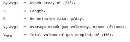
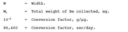
12.0 Data Analysis and Calculations.
12.1 Nomenclature.
12.2
Calculate the equivalent diameter, De, for a rectangular cross section as
follows:
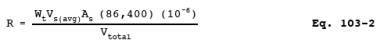
12.3 Calculate the Be
emission rate, R, in g/day for each stack using Equation 103-2. For cyclic
operations, use only the time per day each stack is in operation. The total Be
emission rate from a source is the summation of results from all stacks.
12.4 Test Report. Prepare
a test report that includes as a minimum: A detailed description of the
sampling train used, results of the procedural check described in Section 10.1 with all data and calculations made, all
pertinent data taken during the test, the basis for any estimates made,
isokinetic sampling calculations, and emission results. Include a description
of the test site, with a block diagram and brief description of the process,
location of the sample points in the stack cross section, and stack dimensions
and distances from any point of disturbance.
13.0 Method Performance. [Reserved]
14.0 Pollution Prevention. [Reserved]
15.0 Waste Management. [Reserved]
16.0 References. [Reserved]
17.0 Tables, Diagrams, Flow Charts, and Validation Data.
Figure
103-1. Beryllium Screening Method Sampling Train Schematic.