Method 10 - Determination of Carbon Monoxide Emissions from Stationary Sources
1. PRINCIPLE AND APPLICABILITY
9. CALCULATION--CONCENTRATION OF CARBON MONOXIDE
10. ALTERNATIVE PROCEDURE--INTERFERENCE TRAP
A. Performance
Specifications for NDIR Carbon Monoxide Analyzers.
B. Definitions of
Performance Specifications.
1. PRINCIPLE AND APPLICABILITY
1.1 Principle.
An
integrated or continuous gas sample is extracted from a sampling point and
analyzed for carbon monoxide (CO) content using a Luft-type nondispersive
infrared analyzer (NDIR) or equivalent.
1.2 Applicability.
This
method is applicable for the determination of carbon monoxide emissions from
stationary sources only when specified by the test procedures for determining
compliance with new source performance standards. The test procedure will
indicate whether a continuous or an integrated sample is to be used.
2. RANGE AND SENSITIVITY
2.1
Range. 0 to 1000
ppm.
2.2
Sensitivity. Minimum
detectable concentration is 20 ppm for a 0- to 1000—ppm span.
3. INTERFERENCES
Any
substance having a strong absorption of infrared energy will interfere to some
extent. For example, discrimination ratios for water (H2O) and carbon dioxide (CO2) are 3.5 percent H2O per 7 ppm CO and 10 percent CO2 per 10 ppm CO, respectively, for
devices measuring in the 1500- to 3000-ppm range. For devices measuring in the
0- to 100-ppm range, interference ratios can be as high as 3.5 percent H2O per 25 ppm CO and 10 percent CO2 per 50 ppm CO. The use of silica gel
and ascarite traps will alleviate the major interference problems. The measured
gas volume must be corrected if these traps are used.
4. PRECISION AND ACCURACY
4.1
Precision. The
precision of most NDIR analyzers is approximately ±2 percent of span.
4.2
Accuracy. The
accuracy of most NDIR analyzers is approximately ±5 percent of span after
calibration.
5. APPARATUS
Note:
Mention of trade names or specific products does not constitute endorsement by
the Environmental Protection Agency.
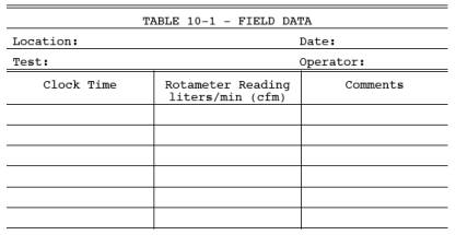
5.1 Continuous Sample
(Figure 10-1).
5.1.1
Probe. Stainless
steel or sheathed Pyrex glass, equipped with a filter to remove particulate
matter.
5.1.2
Air-Cooled Condenser or Equivalent. To
remove any excess moisture.
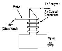
5.2 Integrated Sample
(Figure 10-2).
5.2.1
Probe. Same as in
Section 5.1.1.
5.2.2
Air-Cooled Condenser or Equivalent. Same
as in Section 5.1.2.
5.2.3
Valve. Needle valve,
or equivalent, to adjust flow rate.
5.2.4
Pump. Leak-free
diaphragm type, or equivalent, to transport gas.
5.2.5
Rate Meter. Rotameter,
or equivalent, to measure a flow range from 0 to 1.0 liter per minute (0 to
0.035 cfm).
5.2.6
Flexible Bag. Tedlar,
or equivalent, with a capacity of 60 to 90 liters (2 to 3 ft3). Leak-test the bag in the
laboratory before using by evacuating bag with a pump followed by a dry gas
meter. When evacuation is complete, there should be no flow through the meter.
5.2.7
Pitot Tube. Type S,
or equivalent, attached to the probe so that the sampling rate can be regulated
proportional to the stack gas velocity when velocity is varying with time or a
sample traverse is conducted.
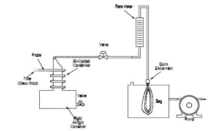
5.3 Analysis
(Figure 10-3).
5.3.1
Carbon Monoxide Analyzer. Nondispersive
infrared spectrometer, or equivalent. This instrument should be demonstrated,
preferably by the manufacturer, to meet or exceed manufacturer's specifications
and those described in this method.
5.3.2
Drying Tube. To
contain approximately 200 g of silica gel.
5.3.3
Calibration Gas. Refer
to Section 6.1.
5.3.4
Filter. As
recommended by NDIR manufacturer.
5.3.5
CO2
Removal Tube. To contain approximately 500 g of
ascarite.
5.3.6
Ice Water Bath. For
ascarite and silica gel tubes.
5.3.7
Valve. Needle valve,
or equivalent, to adjust flow rate.
5.3.8
Rate Meter. Rotameter,
or equivalent, to measure gas flow rate of 0 to 1.0 liter/min (0 to 0.035 cfm)
through NDIR.
5.3.9
Recorder (Optional). To
provide permanent record of NDIR readings.
6. REAGENTS
6.1
Calibration Gases. Known
concentration of CO in nitrogen (N2)
for instrument span, prepurified grade of N2 for
zero, and two additional concentrations corresponding approximately to 60
percent and 30 percent of span. The span concentration shall not exceed 1.5
times the applicable source performance standard. The calibration gases shall
be certified by the manufacturer to be within 2 percent of the specified
concentration.
6.2
Silica Gel. Indicating
type, 6- to 16-mesh, dried at 175°C (347°F) for 2 hours.
6.3
Ascarite. Commercially
available.
7. PROCEDURE
7.1 Sampling.
7.1.1 Continuous Sampling.
Set up the
equipment as shown in Figure 10-1 making sure all connections are leak free.
Place the probe in the stack at a sampling point, and purge the sampling line.
Connect the analyzer, and begin drawing sample into the analyzer. Allow 5
minutes for the system to stabilize, then record the analyzer reading as
required by the test procedure. (See Sections 7.2 and 8). CO2 content of the gas may be determined
by using the Method 3 integrated sampling
procedure, or by weighing the ascarite CO2 removal
tube and computing CO2
concentration from the
gas volume sampled and the weight gain of the tube.
7.1.2 Integrated Sampling.
Evacuate
the flexible bag. Set up the equipment as shown in Figure 10-2 with the bag
disconnected. Place the probe in the stack, and purge the sampling line.
Connect the bag, making sure that all connections are leak free. Sample at a
rate proportional to the stack velocity. CO2 content
of the gas may be determined by using the Method 3 integrated sample
procedures, or by weighing the ascarite CO2 concentration
from the gas volume sampled and the weight gain of the tube.
7.2 CO Analysis.
Assemble
the apparatus as shown in Figure 10-3, calibrate the instrument, and perform
other required operations as described in Section 8. Purge analyzer with N2 prior to introduction of each sample.
Direct the sample stream through the instrument for the test period, recording
the readings. Check the zero and the span again after the test to assure that
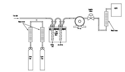
any drift or malfunction is detected. Record the sample data on Table 10-1.
8. CALIBRATION
Assemble
the apparatus according to Figure 10-3. Generally an instrument requires a
warm-up period before stability is obtained. Follow the manufacturer's
instructions for specific procedure. Allow a minimum time of 1 hour for
warm-up. During this time check the sample conditioning apparatus, i.e.,
filter, condenser, drying tube, and CO2 removal
tube, to ensure that each component is in good operating condition. Zero and
calibrate the instrument according to the manufacturer's procedures using, respectively,
N2 and the calibration gases.
9. CALCULATION--CONCENTRATION OF CARBON MONOXIDE
Calculate
the concentration of carbon monoxide in the stack using
Equation
10—1.
![]()
where:
CCO(stack) = Concentration of CO in stack, ppm by
volume, dry basis.
CCO(NDIR) = Concentration of CO measured by
NDIR analyzer, ppm by volume, dry basis.
FCO2 = Volume fraction of CO2 in sample, i.e., percent CO2 from Orsat analysis divided by 100.
10. ALTERNATIVE PROCEDURE--INTERFERENCE TRAP
The sample
conditioning system described in Method 101A, Sections 2.1.2 and 4.2, may be
used as an alternative to the silica gel and ascarite traps.
BIBLIOGRAPHY
1. McElroy, Frank. The Intertech NDIR-CO
Analyzer. Presented at 11th Methods Conference on Air Pollution, University of
California, Berkeley, CA. April 1, 1970.
2. Jacobs, M.B., et al. Continuous
Determination of Carbon Monoxide Infrared Analyzer. J. Air Pollution Control
Association. 9(2):110-114. August 1959.
3. Mine Safety Appliance Co. MSA LIRA Infrared
Gas and Liquid Analyzer Instruction Book. Technical Products Division,
Pittsburgh, PA.
4. Beckman Instruments, Inc. Models
215A, 315A, and 415A Infrared Analyzers. Beckman Instructions 1635-B,
Fullerton, CA. October 1967.
5. Intertech Corporation. Continuous CO
Monitoring System, Model A5611. Princeton,NJ.
6. Bendix Corp. UNOR Infrared Gas
Analyzers. Ronceverte, WV.
Figure 10-1. Continuous Sampling Train
Figure
10-2. Integrated Gas Sampling Train.
Figure
10-3. Analytical Equipment.
ADDENDA
A. Performance Specifications for NDIR Carbon Monoxide Analyzers.
TABLE A-1.
Performance Specifications for NDIR CO Analyzers
————————————————————————————————————
Range
(minimum) 0-1000
ppm
Output
(minimum) 0-10
mV
Minimum
detectable sensitivity 20
ppm
Rise time,
90 percent (maximum) 30
seconds
Fall time,
90 percent (maximum) 30
seconds
Zero drift
(maximum) 10%
in 8 hours
Span drift
(maximum) 10%
in 8 hours
Precision
(maximum) ±2%
of full scale
Noise
(maximum) ±1%
of full scale
Linearity
(maximum deviation) 2%
of full scale
Interference
rejection ratio CO2 - 1000:1; H2O - 500:1
————————————————————————————————————
B. Definitions of Performance Specifications.
1. Range - The minimum and
maximum measurement limits.
2. Output - Electrical signal
which is proportional to the measurement; intended for connection to readout or
data processing devices. Usually expressed as millivolts or milliamps full
scale at a given impedance.
3. Full Scale - The maximum
measuring limit for a given range.
4. Minimum Detectable Sensitivity
- The smallest amount of input concentration that can be detected as the
concentration approaches zero.
5. Accuracy - The degree of agreement
between a measured value and the true value; usually expressed as ± percent of
full scale.
6. Time to 90 Percent Response -
The time interval from a step change in the input concentration at the
instrument inlet to a reading of 90 percent of the ultimate recorded
concentration.
7. Rise Time (90 Percent) - The
interval between initial response time and time to 90 percent response after a
step increase in the inlet concentration.
8. Fall Time (90 Percent) - The
interval between initial response time and time to 90 percent response after a
step decrease in the inlet concentration.
9. Zero Drift - The change in
instrument output over a stated time period, usually 24 hours, of unadjusted
continuous operation when the input concentration is zero; usually expressed as
percent full scale.
10. Span Drift - The change in
instrument output over a stated time period, usually 24 hours, of unadjusted
continuous operation when the input concentration is a stated upscale value;
usually expressed as percent full scale.
11. Precision - The degree of
agreement between repeated measurements of the same concentration, expressed as
the average deviation of the single results from the mean.
12. Noise - Spontaneous deviations
from a mean output not caused by input concentration changes.
13. Linearity - The maximum
deviation between an actual instrument reading and the reading predicted by a
straight line drawn between upper and lower calibration points.