Method 9 - Visual Determination of the Opacity of Emissions from Stationary Sources
1. PRINCIPLE AND
APPLICABILITY
3.1 Certification
Requirements.
3.3 Smoke Generator
Specifications.
INTRODUCTION
(a) Many stationary sources discharge visible
emissions into the atmosphere; these emissions are usually in the shape of a
plume. This method involves the determination of plume opacity by qualified observers.
The method includes procedures for the training and certification of observers
and procedures to be used in the field for determination of plume opacity.
(b) The appearance of a plume as viewed by an
observer depends upon a number of variables, some of which may be controllable
in the field. Variables which can be controlled to an extent to which they no
longer exert a significant influence upon plume appearance include: angle of
the observer with respect to the plume; angle of the observer with respect to
the sun; point of observation of attached and detached steam plume; and angle
of the observer with respect to a plume emitted from a rectangular stack with a
large length to width ratio. The method includes specific criteria applicable
to these variables.
(c) Other variables, which may not be controllable
in the field, are luminescence and color contrast between the plume and the
background against which the plume is viewed. These variables exert an
influence upon the appearance of a plume as viewed by an observer and can
affect the ability of the observer to assign accurately opacity values to the
observed plume. Studies of the theory of plume opacity and field studies have
demonstrated that a plume is most visible and presents the greatest apparent
opacity when viewed against a contrasting background. Accordingly, the opacity
of a plume viewed under conditions where a contrasting background is present
can be assigned with the greatest degree of accuracy. However, the potential
for a positive error is also the greatest when a plume is viewed under such
contrasting conditions. Under conditions presenting a less contrasting
background, the apparent opacity of a plume is less and approaches zero as the
color and luminescence contrast decrease toward zero. As a result, significant
negative bias and negative errors can be made when a plume is viewed under less
contrasting conditions. A negative bias decreases rather than increases the
possibility that a plant operator will be incorrectly cited for a violation of
opacity standards as a result of observer error.
(d) Studies have been undertaken to determine the
magnitude of positive errors made by qualified observers while reading plumes
under contrasting conditions and using the procedures set forth in this method.
The results of these studies (field trials), which involve a total of 769 sets
of 25 readings each, are as follows:
(1) For black plumes
(133 sets at a smoke generator), 100 percent of the sets were read with a
positive error of less than 7.5 percent opacity; 99 percent were read with a
positive error of less than 5 percent opacity. (Note: For a set, positive error
= average opacity determined by observers' 25 observations -average opacity
determined from transmissometer's 25 recordings.)
(2) For white plumes
(170 sets at a smoke generator, 168 sets at a coal-fired power plant, 298 sets
at a sulfuric acid plant), 99 percent of the sets were read with a positive
error of less than 7.5 percent opacity; 95 percent were read with a positive
error of less than 5 percent opacity.
(e) The positive observational error associated with
an average of twenty-five readings is therefore established. The accuracy of
the method must be taken into account when determining possible violations of
applicable opacity standards.
1. PRINCIPLE AND APPLICABILITY
1.1 Principle.
The opacity of
emissions from stationary sources is determined visually by a qualified
observer.
1.2 Applicability.
This method is
applicable for the determination of the opacity of emissions from stationary
sources pursuant to § 60.11(b) and for visually determining opacity of
emissions.
2. PROCEDURES
The observer
qualified in accordance with Section 3 of this method
shall use the following procedures for visually determining the opacity of
emissions.
2.1 Position.
The qualified
observer shall stand at a distance sufficient to provide a clear view of the
emissions with the sun oriented in the 140E sector to his back. Consistent with
maintaining the above requirement, the observer shall, as much as possible,
make his observations from a position such that his line of vision is
approximately perpendicular to the plume direction and, when observing opacity
of emissions from rectangular outlets (e.g., roof monitors, open baghouses,
noncircular stacks), approximately perpendicular to the longer axis of the
outlet. The observer's line of sight should not include more than one plume at
a time when multiple stacks are involved, and in any case the observer should
make his observations with his line of sight perpendicular to the longer axis
of such a set of multiple stacks (e.g., stub stacks on baghouses).
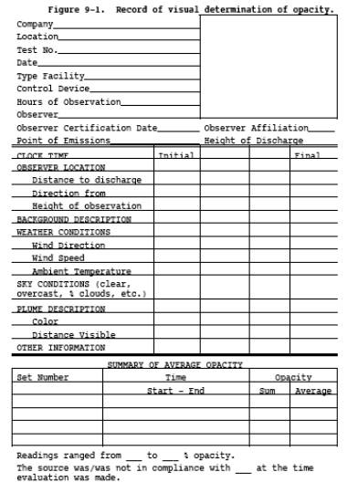
2.2 Field Records.
The observer shall
record the name of the plant, emission location, facility type, observer's name
and affiliation, and the date on a field data sheet (Figure 9-1). The time,
estimated distance to the emission location, approximate wind direction,
estimated wind speed, description of the sky condition (presence and color of
clouds), and plume background are recorded on a field data sheet at the time
opacity readings are initiated and completed.
Figure
9-1. Record of visual determination of opacity.
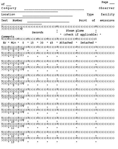
Figure
9-2. Observation record.

2.3 Observations.
Opacity observations
shall be made at the point of greatest opacity in that portion of the plume
where condensed water vapor is not present. The observer shall not look
continuously at the plume but instead shall observe the plume momentarily at
15-second intervals.
2.3.1 Attached Steam Plumes.
When condensed water
vapor is present within the plume as it emerges from the emission outlet,
opacity observations shall be made beyond the point in the plume at which
condensed water vapor is no longer visible. The observer shall record the
approximate distance from the emission outlet to the point in the plume at
which the observations are made.
2.3.2 Detached Steam Plume.
When water vapor in
the plume condenses and becomes visible at a distinct distance from the
emission outlet, the opacity of emissions should be evaluated at the emission
outlet prior to the condensation of water vapor and the formation of the steam
plume.
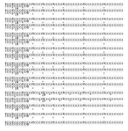
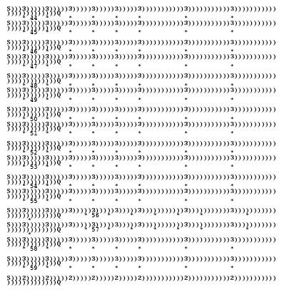
2.4 Recording Observations.
Opacity observations
shall be recorded to the nearest 5 percent at 15-second intervals on an
observational record sheet. (See Figure 9-2 for an
example.) A minimum of 24 observations shall be recorded. Each momentary
observation recorded shall be deemed to represent the average opacity of
emissions for a 15-second period.
2.5 Data Reduction.
Opacity shall be
determined as an average of 24 consecutive observations recorded at 15-second intervals.
Divide the observations recorded on the record sheet into sets of 24
consecutive observations. A set is composed of any 24 consecutive observations.
Sets need not be consecutive in time and in no case shall two sets overlap. For
each set of 24 observations, calculate the average by summing the opacity of
the 24 observations and dividing this sum by 24. If an applicable standard
specifies an averaging time requiring more than 24 observations, calculate the
average for all observations made during the specified time period. Record the
average opacity on a record sheet. (See Figure 9-1 for an
example.)
3. QUALIFICATION AND TESTING
3.1 Certification Requirements.
To receive
certification as a qualified observer, a candidate must be tested and
demonstrate the ability to assign opacity readings in 5 percent increments to
25 different black plumes and 25 different white plumes, with an error not to
exceed 15 percent opacity on any one reading and average error not to exceed
7.5 percent opacity in each category. Candidates shall be tested according to
the procedures described in Section 3.2. Smoke generators used pursuant to
Section 3.2 shall be equipped with a smoke meter which meets the requirements
of Section 3.3. The certification shall be valid for a period of 6 months, at
which time the qualification procedure must be repeated by any observer in
order to retain certification.
3.2 Certification Procedure.
The certification test
consists of showing the candidate a complete run of 50 plumes--25 black plumes
and 25 white plumes-generated by a smoke generator. Plumes within each set of
25 black and 25 white runs shall be presented in random order. The candidate
assigns an opacity value to each plume and records his observation on a
suitable form. At the completion of each run of 50 readings, the score of the
candidate is determined. If a candidate fails to qualify, the complete run of
50 readings must be repeated in any retest. The smoke test may be administered
as part of a smoke school or training program and may be preceded by training
or familiarization runs of the smoke generator during which candidates are
shown black and white plumes of known opacity.
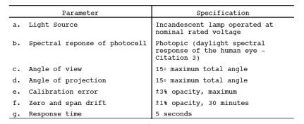
3.3 Smoke Generator Specifications.
Any smoke generator
used for the purposes of Section 3.2 shall be equipped with a smoke meter
installed to measure opacity across the diameter of the smoke generator stack.
The smoke meter output shall display in-stack opacity based upon a path length
equal to the stack exit diameter, on a full 0 to 100 percent chart recorder
scale. The smoke meter optical design and performance shall meet the
specifications shown in Table 9-1. The smoke meter shall
be calibrated as prescribed in Section 3.3.1 prior to the conduct of each smoke
reading test. At the completion of each test, the zero and span drift shall be
checked and if the drift exceeds ±l percent opacity, the condition shall be
corrected prior to conducting any subsequent test runs. The smoke meter shall
be demonstrated, at the time of installation, to meet the specifications listed
in Table 9-1. This demonstration shall be repeated following any subsequent
repair or replacement of the photocell or associated electronic circuitry
including the chart recorder or output meter, or every 6 months, whichever
occurs first.
TABLE
9-1 - SMOKE METER DESIGN AND PERFORMANCE SPECIFICATIONS
3.3.1 Calibration.
The smoke meter is calibrated
after allowing a minimum of 30 minutes warm-up by alternately producing
simulated opacity of 0 percent and 100 percent. When stable response at 0
percent or 100 percent is noted, the smoke meter is adjusted to produce an
output of 0 percent or 100 percent, as appropriate. This calibration shall be
repeated until stable 0 percent and 100 percent opacity values may be produced
by alternately switching the power to the light source on and off while the
smoke generator is not producing smoke.
3.3.2 Smoke Meter
Evaluation. The smoke meter design
and performance are to be evaluated as follows:
3.3.2.1 Light
Source. Verify from
manufacturer's data and from voltage measurements made at the lamp, as
installed, that the lamp is operated within ±5 percent of the nominal rated
voltage.
3.3.2.2 Spectral
Response of Photocell. Verify
from manufacturer's data that the photocell has a photopic response; i.e., the
spectral sensitivity of the cell shall closely approximate the standard
spectral luminosity in (b) of Table 9-1.
3.3.2.3 Angle of
View. Check construction
geometry to ensure that the total angle of view of the smoke plume, as seen by
the photocell, does not exceed 15°. The total angle of view may be calculated
from: • = 2 tan -1 (d/2L), where • = total angle of view; d = the sum of the
photocell diameter + the diameter of the limiting aperture; and L = the
distance from the photocell to the limiting aperture. The limiting aperture is
the point in the path between the photocell and the smoke plume where the angle
of view is most restricted. In smoke generator smoke meters this is normally an
orifice plate.
3.3.2.4 Angle of
Projection. Check construction
geometry to ensure that the total angle of projection of the lamp on the smoke
plume does not exceed 15°. The total angle of projection may be calculated
from: • = 2 tan-1 (d/2L), where • = total angle of projection; d =
the sum of the length of the lamp filament + the diameter of the limiting
aperture; and L = the distance from the lamp to the limiting aperture.
3.3.2.5
Calibration Error. Using
neutral-density filters of known opacity, check the error between the actual
response and the theoretical linear response of the smoke meter. This check is
accomplished by first calibrating the smoke meter according to Section 3.3.1
and then inserting a series of three neutral-density filters of nominal opacity
of 20, 50, and 75 percent in the smoke meter path length. Filters calibrated
within 2 percent shall be used. Care should be taken when inserting the filters
to prevent stray light from affecting the meter. Make a total of five
nonconsecutive readings for each filter. The maximum error on any one reading
shall be 3 percent opacity.
3.3.2.6 Zero and
Span Drift. Determine the zero
and span drift by calibrating and operating the smoke generator in a normal
manner over a 1-hour period. The drift is measured by checking the zero and
span at the end of this period.
3.3.2.7 Response
Time. Determine the response
time by producing the series of five simulated 0 percent and 100 percent
opacity values and observing the time required to reach stable response.
Opacity values of 0 percent and 100 percent may be simulated by alternately
switching the power to the light source off and on while the smoke generator is
not operating.
4. BIBLIOGRAPHY
1. Air Pollution Control District Rules and
Regulations, Los Angeles County Air Pollution Control District, Regulation IV,
Prohibitions, Rule 50.
2. Weisburd, Melvin I., Field Operations and
Enforcement Manual for Air, U.S. Environmental Protection Agency, Research
Triangle Park, NC, APTD-1100, August 1972, pp. 4.1-4.36.
3. Condon. E.U., and Odishaw, H., Handbook of
Physics, McGraw-Hill
Co., New York, NY,
1958, Table 3.1, p. 6-52.